Enabling switch – Beijer Electronics M70 EN User Manual
Page 18
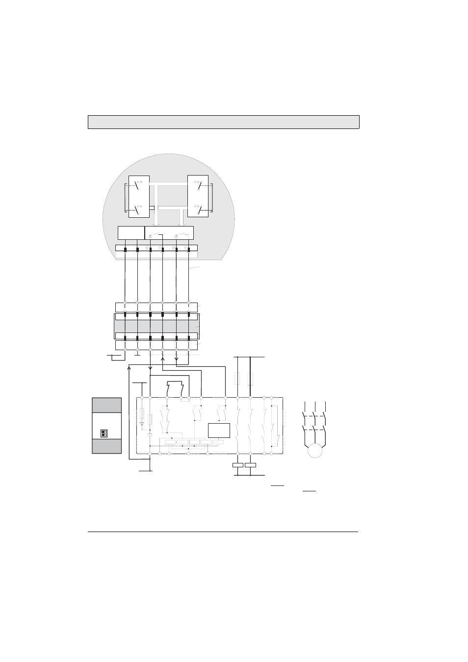
Enabling Switch
18
Beijer Electronics, MAEN843A
Connection with ELAN SRB-NA-R-C.27/S1 Control Relay
See also chapters
14.4 Pin Description of X1 Ter-
F2
F1
S1
K1
K2
K3
K1
K1
K2
K3
K3
K2
K1
L1
N
GND
+24VDC
Rear side of
component
1
0
1
0
S4
S1
KA
KB
KA
KB
min. 0,3 mm² Cu
+24VDC
KA
KB
L1
L2
L3
M
GND
1
2
3
4
1
2
3
4
DC/DC
converter
6
7
6
7
S19:
K3:
+24V
GND
ED1+
ED1-
ED2+
ED2-
X1
+24V
GND
ED1+
ED1-
ED2+
ED2-
K4:
K3:
Terminal block socket K3
on connection box
Connection box
Male connector X2
on conncection box
Terminal block socket K4
on connection box
Connection cable
CAB TTxxx
Evaluation electronics
Circuit 1
Circuit 2
Female connector X1
on connection box
M70
(2 enabling switches with
3 positions and 2 circuits each)
Enabling of
dangerous
movement!
Notes:
1) All contacts of KA and KB must be forced-guided.
2) S4 and S1 on the rear side of the component must be set to the position 0.
Short-circuit
detection
S4
1 2 3
1 2 3
ZT
L1
ZT
L2
ZT
L
ZT
R1
ZT
R2
ZT
R
3 2 1
3 2 1
X2
D
D2
L13
L11
L14
14
24
34
42
41
33
23
13
S41
S21
S13
S12
S11
C
C1
K1
K3
K2