2 rs232c connection, 1 rs232c wiring diagram, Rs232c connection – Beijer Electronics M70 EN User Manual
Page 12: Connection
Connection
12
Beijer Electronics, MAEN843A
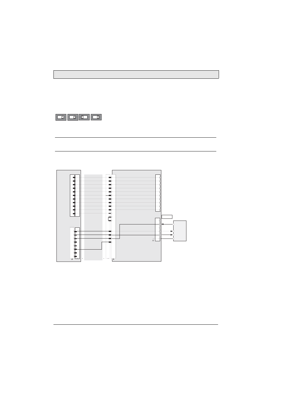
4.2 RS232C Connection
The serial interface is used as an RS232C interface. The dip switches has to be
set according to below for RS232C communication:
The COM-SIO connector S11 in the cable entrance area of the M70 is used.
4.2.1 RS232C Wiring Diagram
Note:
The RS232C connection cannot be used simultaneously with an Ethernet connection.
B5
B4
B2
B3
1
2
3
4
6
8
9
10
11
7
1
2
3
6
S6
S1
1
K2
5
X1
ENABLE_ED2-
ENABLE_ED2+
ENABLE_ED1-
ENABLE_ED1+
E-STOP_ES2-
E-STOP_ES2+
E-STOP_ES1-
E-STOP_ES1+
GND
+24 V DC
1
2
3
4
5
6
7
8
9
10
13
14
15
16
K1
M70
S22 K3
K1
TxD
RxD
RxD
TxD
1
2
3
4
5
6
X3
SHIELD
RS-232-C
External device
TxD
RxD
GND
brown
yellow
green
grey
pink
brown-green
white-green
grey-pink
red-blue
black
violet
blue
white
orange
red
24 VDC
GND_IN
Enabling switch, circuit 1, pos.
Emergency stop, circuit 1
Emergency stop, circuit 1
Emergency stop, circuit 2
Emergency stop, circuit 2
Enabling switch, circuit 1, neg.
Enabling switch, circuit 2, pos.
Enabling switch, circuit 2, neg.
Connection box CB211
Connection cable
CABTTxxx
RTS
1
2
3
4
5
6
7
8
12
17
CTS
RTS
11
9
10