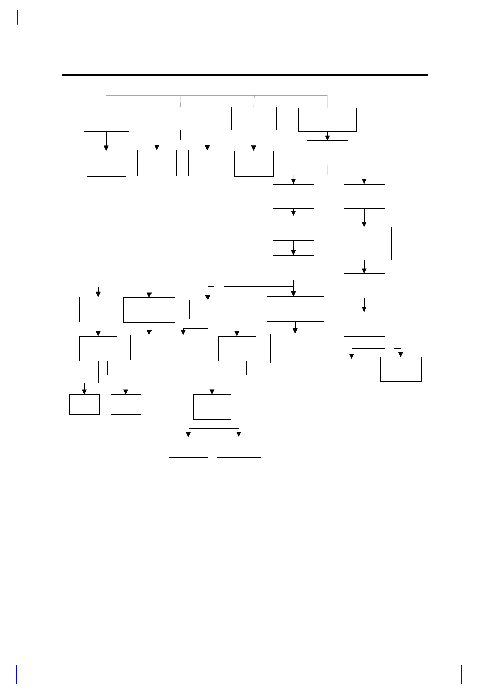
Disassembly sequence flowchart, Disassembly and unit replacement 3-5, Figure 3-3 disassembly sequence flowchart – Acer 365 User Manual
Page 55
Disassembly and Unit Replacement
3-5
Battery
Modem
Module
DIMM
HDD
Open
Dimm Door
Open
Battery Door
Remove
HDD Cover
Remove
Display Hinge
Unplug K/B
conector
Remove
K/B
Remove
LED Cover
Remove
Heat Sink
Unplug Cables
(FDD/CD-ROM)
CPU
EMI Bracket
Lower
Case
Unplug
Cables
CPU
Board
Upper
Case
Keyboard
Board
Remove
FDD/CD-ROM
DC-DC
Covert Bd
M/B
Audio
Board
Speaker
Touch
Pad
PCMCIA
Socket
Charger
Board
Unplug
LCD Cable
/Inverter Cable
Display
Module
Display
Bazel
Inverter
Board
Remove
LED Cover
LCD
Pannel
Bx2
(for TFT LCD only)
Dx4
E
x4
Bx1
C
x4
Ix2
Ix2
Jx2, Gx2
Bx2
Hx2
Fx3
Dx8
Gx2
Figure 3-3
Disassembly Sequence Flowchart
See also other documents in the category Acer Notebooks:
- Aspire 5741ZG (2345 pages)
- Aspire 5741ZG (313 pages)
- TravelMate 5330 (14 pages)
- Extensa 7230 (86 pages)
- AOD257 (1810 pages)
- AO753 (374 pages)
- AO533 (4 pages)
- AOD255 (299 pages)
- AO522 (1810 pages)
- Aspire V5-531G (2484 pages)
- Aspire EC-471G (10 pages)
- Aspire M3-581TG (11 pages)
- Aspire M3-581PTG (10 pages)
- Aspire M3-581TG (3478 pages)
- Aspire 8950G (378 pages)
- Aspire EC-471G (11 pages)
- Aspire V5-571PG (3604 pages)
- Aspire E1-571 (308 pages)
- Aspire E1-521 (11 pages)
- Aspire S5-391 (111 pages)
- Aspire S5-391 (11 pages)
- Aspire M5-581TG (10 pages)
- Aspire M5-581TG (11 pages)
- Aspire V3-471G (362 pages)
- Aspire V3-471G (11 pages)
- Aspire M5-481TG (11 pages)
- Aspire 9420 (109 pages)
- Aspire 9520 (123 pages)
- 3280 (106 pages)
- 4600 (128 pages)
- Aspire 1300 (96 pages)
- 4330 (198 pages)
- TravelMate 3250 (98 pages)
- 1450 (99 pages)
- 2420 (108 pages)
- 310 (2 pages)
- 310 (130 pages)
- 3690 (123 pages)
- 5010 (113 pages)
- 3250 (124 pages)
- 5560 (112 pages)
- 5230 (176 pages)
- 420 series (78 pages)
- 3000 (109 pages)
- 3200 Series (90 pages)