3 disassembly, Sequence, Guide to disassembly sequence – Acer 365 User Manual
Page 54: 3 disassembly sequence
3-4
Service Guide
3.1.3 Disassembly
Sequence
The disassembly procedure described in this manual is divided into four major sections:
•
Section 4.2:
Installing memory
•
Section 4.3:
Removing the modem board
•
Section 4.4:
Removing the hard disk drive
•
Section 4.5:
Removing the keyboard
•
Section 4.6:
Disassembling the inside frame assembly
•
Section 4.7:
Disassembling the display
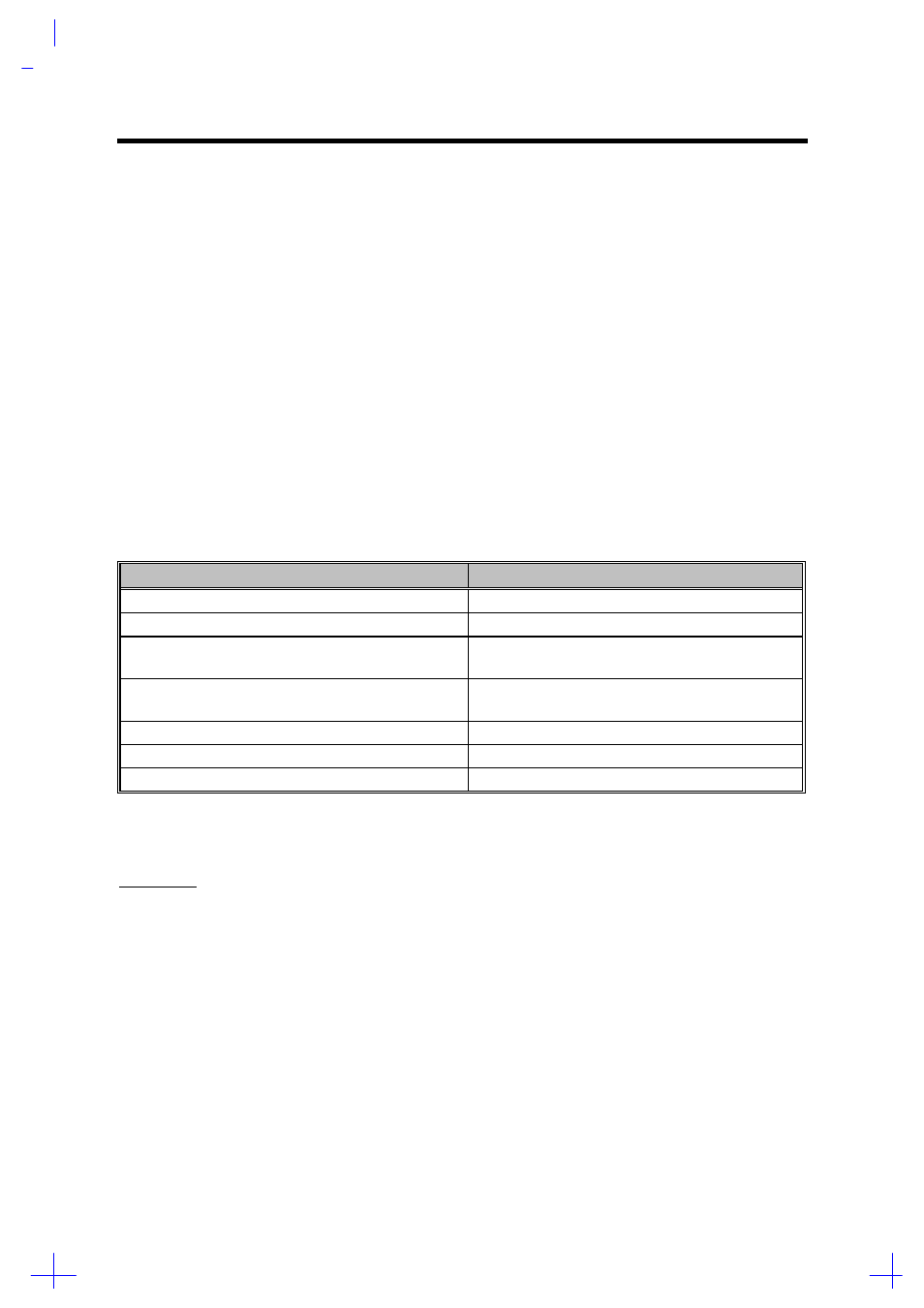
The following table lists the components that need to be removed during servicing. For example, if
you want to remove the motherboard, you must first remove the keyboard, then disassemble the
inside assembly frame in that order.
Table 3-1
Guide to Disassembly Sequence
Service Item
Prerequisite
Remove or replace the hard disk drive
Remove or replace the internal module
Remove the keyboard (and heat sink assembly).
Remove the motherboard for service or replacement
1.
Remove the keyboard.
2.
Disassemble the housing.
Remove the touchpad
1.
Remove the keyboard.
2.
Disassemble the housing.
Replace the LCD
Remove the display.
Install CPU
Remove the keyboard (and heat sink assembly).
Install additional memory
The flowchart on the succeeding page gives a clearer and more graphic representation on the entire
disassembly sequence. Please refer to it from time to time, together with the screw list below.
SCREW LIST
•
A screw
M2x4L Black
(p/n: 86.1A322.4R0)
•
B screw
M2x6L NI
(p/n: 86.1A522.6R0)
•
C screw
M2x20L NI
(p/n: 86.1A522.200)
•
D screw
M2.5x8L NYLOK B-ZN
(p/n: 86.1A353.8R0)
•
E screw
M2.5x6L NYLOK NI
(p/n:86.1A553.6R0)
•
F screw
M3x6L BIND NI
(p/n:86.4A524.6R0)
•
G screw
M2.5x4L BLACK.NY
(p/n: 86.1A553.4R0)
•
H screw
M2x14L NI
(p/n: 86.1A522.140)
•
I screw
M2x4L NI
(p/n: 86.1A522.4R0)
•
J screw cap
M2*L5 NI
(p/n: 86.7A522.5R0)