Hardware configuration and specification, Memory address map, Interrupt channel map – Acer 365 User Manual
Page 14: 3 hardware configuration and specification, 2 interrupt channel map
1-4
Service Guide
1.3
Hardware Configuration and Specification
1.3.1
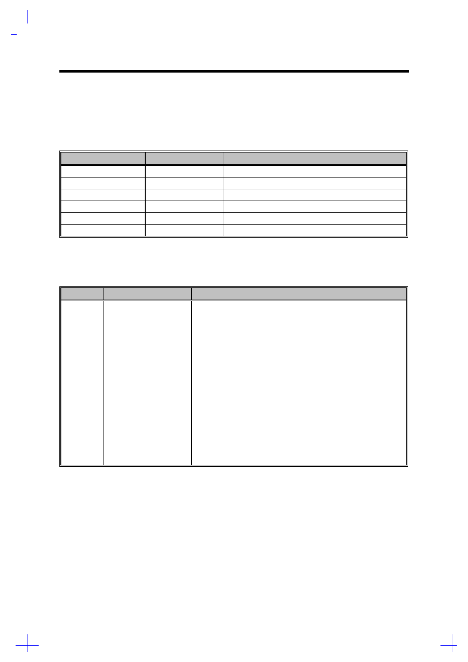
Memory Address Map
Table 1-2
Memory Address Map
Address Range
Definition
Function
000000 - 09FFFF
640 KB memory
Base memory
0A0000 - 0BFFFF
128 KB video RAM
Reserved for graphics display buffer
0C0000 - 0CBFFF
Video BIOS
Video BIOS
0F0000 - 0FFFFF
64 KB system BIOS
System BIOS
100000 - top limited
Extended memory
SIMM memory
FE0000 - FFFFFF
256 KB system ROM
Duplicate of code assignment at 0E0000-0FFFFF
1.3.2
Interrupt Channel Map
Table 1-3
Interrupt Channel Map
Priority
Interrupt Number
Interrupt Source
1
2
3
4
5
6
7
8
9
10
11
12
13
14
15
16
17
18
19
SMI
NMI
IRQ 0
IRQ 1
IRQ 2
IRQ 8
IRQ 9
IRQ 10
IRQ 11
IRQ 12
IRQ 13
IRQ 14
IRQ 15
IRQ 3
IRQ 4
IRQ 5
IRQ 6
IRQ 7
Power management unit
Parity error detected, I/O channel error
Interval timer, counter 0 output
Keyboard
Interrupt from controller 2 (cascade)
Real-time clock /
Cascaded to INT 0AH (IRQ 2) / Audio / PCMCIA/Internal Modem
Audio (option) / PCMCIA / Internal modem / Serial communication
port 2 / PCMCIA / USB
Audio (option) / PCMCIA / Internal modem / Serial communication
port 1 / PCMCIA
PS/2 mouse
INT from coprocessor
Hard disk controller / PCMCIA controller
CD-ROM controller / PCMCIA controller
Serial communication port 2 / Internal modem / Audio / PCMCIA
Serial communication port 1 / Internal modem / Audio / PCMCIA
Parallel port (option) / Audio / PCMCIA
Diskette controller
Parallel port (option) / Audio / Internal Modem