Power management block diagram, 18 service guide, Figure 1-3 power management block diagram – Acer 365 User Manual
Page 28
1-18
Service Guide
MultiBoot
The system can boot from the FDD, External FDD, HDD, or CD-ROM. The user can select the
desired booting process to boot the system. If the CD-ROM is bootable, the BIOS will override the
other process to boot the system directly.
Power Management
This computer has a built-in power management unit that monitors system activity. System activity
refers to any activity involving one or more of the following devices: keyboard, mouse, floppy drive,
hard disk, peripherals connected to the serial and parallel ports, and video memory. If no activity is
detected for a period of time (called an inactivity time-out), the computer stops some or all of these
devices in order to conserve energy.
This computer employs an innovative power management technique called Heuristic Power
Management or HPM. HPM allows the computer to provide maximum power conservation and
maximum performance at the same time.
Power management methods used by most computers are timer-based. You set inactivity time-out
values for the display, hard disk, and other devices. The computer then "sleeps" when these time-
outs elapse. The problem with this is that no two users are alike. Each of us has his or her own
habits when using the computer, which makes timer-based power management ineffective.
With HPM, your computer manages its power according to the way you use your computer. This
means the computer delivers maximum power when you need it, and saves power when you don’t
need the maximum — all without your intervention. There are no timers to set, because the HPM
system figures out everything for you.
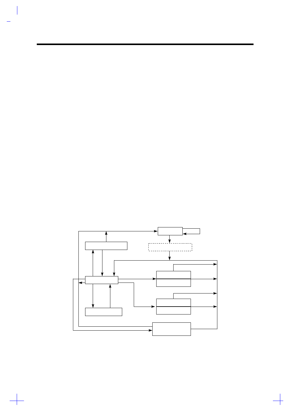
HDD Standby Timer Time Out
Idle of HDD
Power Off
Display Screen Off
Normal Mode
Hibernation Mode
Standby Mode
Standby Mode
HDD Standby Mode
(HDD Motor Off)
Light Green Mode
Light Green Mode
Check password if needed
Power Switch Off More than 3 Seconds
Cover Door Close
Power Switch On
K/B, PS/2 Mouse Pressed
Standby Event
System Active
Power Switch (Beep)
Standby Wakeup
Cover Door Close
Power Switch (Beep)
Cover Door Open
Power Switch
Event
Display Standby
Timer Time Out
Hibernation
Event
HDD Acess
Figure 1-3
Power Management Block Diagram