Drive motor installation, Motor rotation, Motor installation – Pulsafeeder Pulsar Shadow User Manual
Page 18: Electrical, 7 drive motor installation, 1 motor rotation, 2 motor installation, 3 electrical
4.7 Drive Motor Installation
4.7.1 Motor
Rotation
Motor can be operated in either direction, clockwise or counterclockwise. Verification of motor
direction is not necessary at startup.
4.7.2 Motor
Installation
PULSAR Shadow
®
pumps may be shipped with the drive motor packed separately. This is
done to avoid damage during transport.
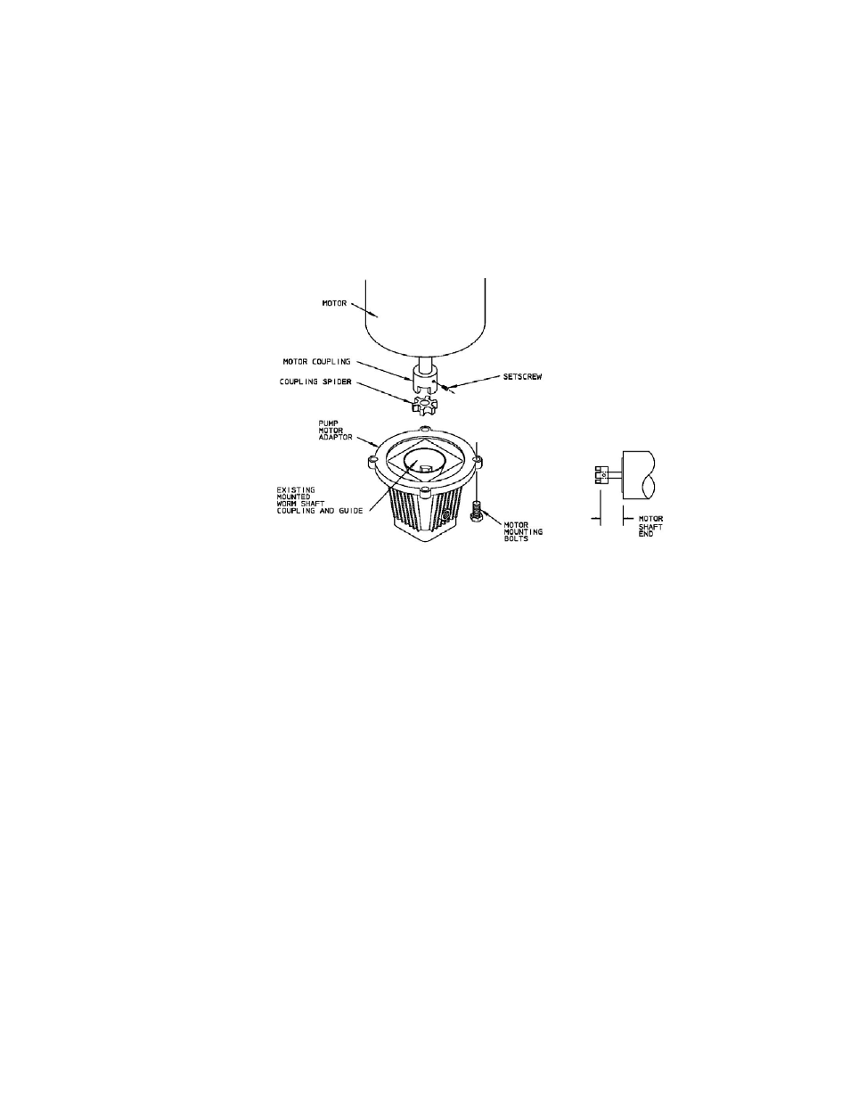
Figure 11
1. Remove the unattached coupling half from the motor adaptor. Ensure that the
elastomer coupling spider remains in place, on the coupling half that remains attached
to the worm shaft.
2. If applicable, remove any tape or retainer rings that hold the motor shaft key in place.
3. Place the loose coupling half on the motor shaft. Align the keyway with the key and
align shaft end to inner coupling surface as shown in figure above.
4. Tighten the setscrew onto the shaft key.
5. Place the motor in a vertical position and align the coupling teeth.
6. Install the motor downwards onto the adaptor. The plastic guide will assist in aligning
the coupling halves. Final position can be achieved by slightly rotating the motor until
the coupling jaws align.
7. Rotate the motor until the clearance holes in the adaptor and the tapped holes in the
motor align. Fasten the motor to the adaptor using the supplied bolts (4). Tighten bolts
evenly to secure motor.
4.7.3 Electrical
Wire the PULSAR Shadow
®
drive motor according to the motor vendor’s nameplates and
instructions, and according to any appropriate national and local electrical codes and
regulations.
If the motor is to be utilized with a Pulsafeeder controller, such as the DLC or DLCM, consult
the appropriate Pulsafeeder IOM for further motor wiring instructions.
12