Typical wiring path for roof mounted units, Wheel rotation, Final steps – COOK QMX User Manual
Page 5: Operation, Start up, Inspection, Final installation steps
5
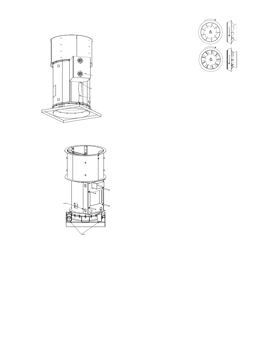
Typical Wiring Path for Roof Mounted Units
For sizes 135-600, route conduit under motor cover
between the motor support rails and out to enclosure as
shown in Figure 1 below.
For sizes 90-120, route conduit through holes in the
sides of the motor support saddle as shown in Figure 2
below.
Wheel Rotation
Test the fan to ensure the rotation of the wheel is the
same as indicated by the arrow marked Rotation.
115 and 230 Single Phase Motors
Fan wheel rotation is set correctly at the factory. Chang-
ing the rotation of this type of motor should only be
attempted by a qualified electrician.
208, 230, and 460, 3 Phase Motors
These motors are electrically reversible by switching
two of the supply leads. For this reason, the rotation of the
fan cannot be restricted to one direction at the factory. See
Wiring Diagrams for specific information on reversing
wheel direction.
Do not allow the fan to run in the wrong direction.
This will overheat the motor and cause serious dam-
age. For 3-phase motors, if the fan is running in the
wrong direction, check the control switch. It is possi-
Weather Cover
Liquidtite
Size 135-600, Run
Liquidtite Between
Weather Cover and Unit
Figure 1
Enclosure May Be Located
in Either Corner
(Liquidtite Not Shown)
90-120, Run
Liquidtite Through
Holes in Saddle
Figure 2
ble to interchange two leads at this location so that the
fan is operating in the correct direction.
Final Installation Steps
a. Inspect fasteners and setscrews, particularly fan
mounting and bearing fasteners, and tighten accord-
ing to the recommended torque shown in the table
Recommended Torque for Setscrews/Bolts.
b. Inspect for correct voltage with voltmeter.
c. Ensure all accessories are installed.
Operation
Pre-Start Checks
a. Lock out all the primary and secondary power
sources.
b. Ensure fasteners and setscrews, particularly those
used for mounting the fan, are tightened.
c. Inspect belt tension and pulley alignment.
d. Inspect motor wiring.
e. Ensure belt touches only the pulley.
f. Ensure fan and ductwork are clean and free of debris.
g. Inspect wheel-to-inlet clearance. The correct wheel-
to-inlet clearance is critical to proper fan performance.
h. Close and secure all access doors.
g. Restore power to the fan.
Start Up
Turn the fan on. In variable speed units, set the fan to its
lowest speed and inspect for the following:
• Direction of rotation.
• Excessive vibration.
• Unusual noise.
• Bearing noise.
• Improper belt alignment or tension (listen for squeal-
ing).
• Improper motor amperage or voltage.
If a problem is discovered, immediately shut the fan
off. Lock out all electrical power and check for the
cause of the trouble. See Troubleshooting.
Inspection
Inspection of the fan should be conducted at the first 30
minute, 8 hour and 24 hour intervals of satisfactory opera-
tion. During the inspections, stop the fan and inspect as per
the Conditions Chart.
30 Minute Interval
Inspect bolts, setscrews, and motor mounting bolts.
Adjust and tighten as necessary.
8 Hour Interval
Inspect belt alignment and tension. Adjust and tighten as
necessary.
24 Hour Interval
Inspect belt tension. Adjust and tighten as necessary.
QMX
QMX-HP