Wheel, Belt, Wheel-to-inlet clearance – COOK TCN User Manual
Page 3: Belt and pulley installation, Wiring installation
3
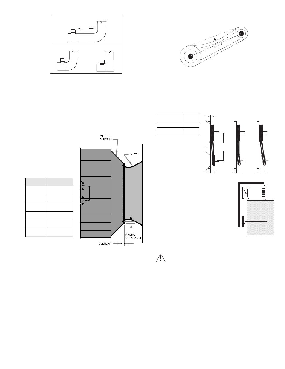
Wheel-to-Inlet Clearance
The correct wheel-to-inlet clearance is critical to proper
fan performance. This clearance should be verified before
initial start-up since rough handling during shipment could
cause a shift in fan components. Refer to wheel/inlet draw-
ing below for correct overlap.
Adjust the overlap by loosening the wheel hub and mov-
ing the wheel along the shaft to obtain the correct value.
A uniform radial gap
(space between the edge
of the cone and the edge
of the inlet) is obtained by
loosening the inlet cone
bolts and repositioning the
inlet cone.
Belt and Pulley
Installation
Belt tension is determined by the sound the belts make
when the fan is first started. Belts will produce a loud
squeal which dissipates after the fan is operating at full
capacity. If the belt tension is too tight or too loose, lost effi-
ciency and possible damage can occur.
Do not change the pulley pitch diameter to change ten-
sion. This will result in a different fan speed.
a. Loosen motor plate adjustment bolts and move motor
plate in order that the belts can easily slip into the
grooves on the pulleys. Never pry, roll, or force the
belts over the rim of the pulley.
b. Adjust the motor plate until proper tension is reached.
For proper tension, a deflection of approximately 1/4”
per foot of center distance should be obtained by
firmly pressing the belt. Refer to Figure 3.
Size
Overlap
60 - 165
3/16”
180 - 245
1/4”
270 - 300
5/16”
330 - 365
3/8”
402
7/16”
445 - 490
1/2”
Discharge Duct Turns
Correct
Incorrect
Min 3
Dia.
c. Lock the motor plate adjustment nuts in place.
d. Ensure pulleys are properly aligned. Refer to Figure 4.
Pulley Alignment
Pulley alignment is adjusted by loosening the motor pulley
setscrew and by moving the motor pulley on the motor shaft.
Figure 4 indicates where to measure the allowable gap for
the drive alignment tolerance.
All contact points (indicated by WXYZ)
are to have a gap less than the toler-
ance shown in the table. When the pul-
leys are not the same width, the
allowable gap must be adjusted by half
of the difference in width (As shown in
A & B of Figure 4). Figure 5 illustrates
using a carpenter’s square to adjust
the position of the motor pulley until
the belt is parallel to the longer leg of
the square.
Wiring Installation
NOTICE! All wiring should be in accordance
with local ordinances and the National Electri-
cal Code, NFPA 70. Ensure the power supply
(voltage, frequency, and current carrying capac-
ity of wires) is in accordance with the motor
nameplate.Lock off all power sources before
unit is wired to power source.
Leave enough slack in the wiring to allow for motor
movement when adjusting belt tension. Some fractional
motors have to be removed in order to make the connec-
tion with the terminal box at the end of the motor. To
remove motor, remove bolts securing motor base to power
assembly. Do not remove motor mounting bolts.
1 foot
1/4 inch
Figure 3
Figure 4
Tolerance
Center Distance
Maximum
Gap
Up thru 12”
1/16”
12” up through 48
1/8”
Over 48”
1/4”
OFFSET
ANGULAR
OFFSET/ANGULAR
A
W
X
Y
Z
B
CENTER
DISTANCE
(CD)
GAP
GAP
Figure 5