Operation, Maintenance, Final installation steps – COOK IMH User Manual
Page 5: Start up, Inspection
5
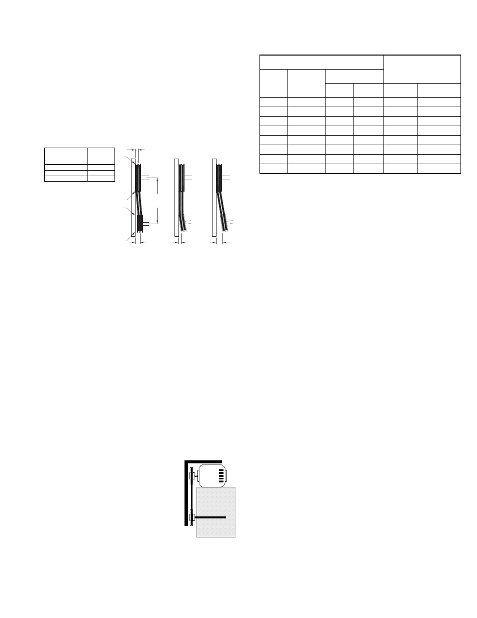
Pulley Alignment
Pulley alignment is adjusted by loosening the motor pulley
setscrew and by moving the motor pulley on the motor
shaft.
Figure 4 indicates where to measure the allowable gap
for the drive alignment tolerance. All contact points (indi-
cated by WXYZ) are to have a gap less than the tolerance
shown in the table.
When the pulleys are not the same width, the allowable
gap must be adjusted by half of the difference in width. Fig-
ure 5 illustrates using a carpenter’s square to adjust the
position of the motor pulley until the belt is parallel to the
longer leg of the square.
Final Installation Steps
a. Inspect fasteners and setscrews, particularly fan
mounting and bearing fasteners, and tighten accord-
ing to the recommended torque shown in the table
Recommended Torque for Setscrews/Bolts.
b. Inspect for correct voltage with voltmeter.
c. Ensure all accessories are installed.
Operation
Pre-Start Checks
a. Lock out all the primary and secondary power
sources.
b. Ensure fasteners and setscrews, particularly those
used for mounting the fan, are tightened.
c. Inspect belt tension and pulley alignment.
d. Inspect motor wiring.
e. Ensure belt touches only the pulley.
f. Ensure fan and ductwork are clean and free of debris.
g. Inspect wheel-to-inlet clearance. The correct wheel-
to-inlet clearance is critical to proper fan performance.
h. Close and secure all access doors.
g. Restore power to the fan.
Start Up
Turn the fan on. In variable speed
units, set the fan to its lowest speed and
inspect for the following:
• Direction of rotation.
• Excessive vibration.
• Unusual noise.
• Bearing noise.
• Improper belt alignment or tension (listen for squeal-
ing).
• Improper motor amperage or voltage.
If a problem is discovered, immediately shut the fan
Figure 4
Tolerance
Center Distance
Maximum
Gap
Up thru 12”
1/16”
12” up through 48
1/8”
Over 48”
1/4”
OFFSET
ANGULAR
OFFSET/ANGULAR
A
W
X
Y
Z
B
CENTER
DISTANCE
(CD)
GAP
GAP
off. Lock out all electrical power and check for the-
cause of the trouble. See Troubleshooting.
Inspection
Inspection of the fan should be conducted at the first 30
minute, 8 hour and 24 hour intervals of satisfactory opera-
tion. During the inspections, stop the fan and inspect as per
the Conditions Chart.
30 Minute Interval
Inspect bolts, setscrews, and motor mounting bolts.
Adjust and tighten as necessary.
8 Hour Interval
Inspect belt alignment and tension. Adjust and tighten as
necessary.
24 Hour Interval
Inspect belt tension, bolts, setscrews, and motor adjust-
ing bolts. Adjust and tighten as necessary.
Maintenance
Establish a schedule for inspecting all parts of the fan.
The frequency of inspection depends on the operating con-
ditions and location of the fan.
Inspect fans exhausting corrosive or contaminated air
within the first month of operation. Fans exhausting con-
taminated air (airborne abrasives) should be inspected
every three months.
Regular inspections are recommended for fans exhaust-
ing non-contaminated air.
It is recommended the following inspection be conducted
twice per year.
• Inspect bolts and setscrews for tightness. Tighten as
necessary. Worn setscrews should be replaced imme-
diately.
• Inspect belt wear and alignment. Replace worn belts
with new belts and adjust alignment as needed. See
Belt and Pulley Installation, page 3.
• Bearings should be inspected as recommended in the
Conditions Chart.
• Inspect variable inlet vanes for freedom of operation
and excessive wear. The vane position should agree
with the position of the control arm. As the variable inlet
vanes close, the entering air should spin in the same
direction as the wheel.
• Inspect springs and rubber isolators for deterioration
and replace as needed.
• Inspect for cleanliness. Clean exterior surfaces only.
Recommended Torque for Setscrews/Bolts
Setscrews
Hold Down Bolts
Size
Key Hex
Across
Flats
Recommended
Torque
Min.
Max.
Size
Wrench
Torque
No.10
3/32”
28
33
3/8”-16
240
1/4”
1/8”
66
80
1/2”-13
600
5/16”
5/32”
126
156
5/8”-11
1200
3/8”
3/16”
228
275
3/4”-10
2100
7/16”
7/32”
348
384
7/8”- 9
2040
1/2”
1/4”
504
600
1”- 8
3000
5/8”
5/16”
1104
1200
1-1/8” - 7
4200
3/4”
3/8”
1440
1800
1-1/4” - 7
6000
(IN/LB.)
Figure 5