Duct installation – COOK IMH User Manual
Page 2
2
Duct Installation
Efficient fan performance relies on the proper installation
of inlet and discharge ducts. Be sure your fan conforms to
the guidelines below.
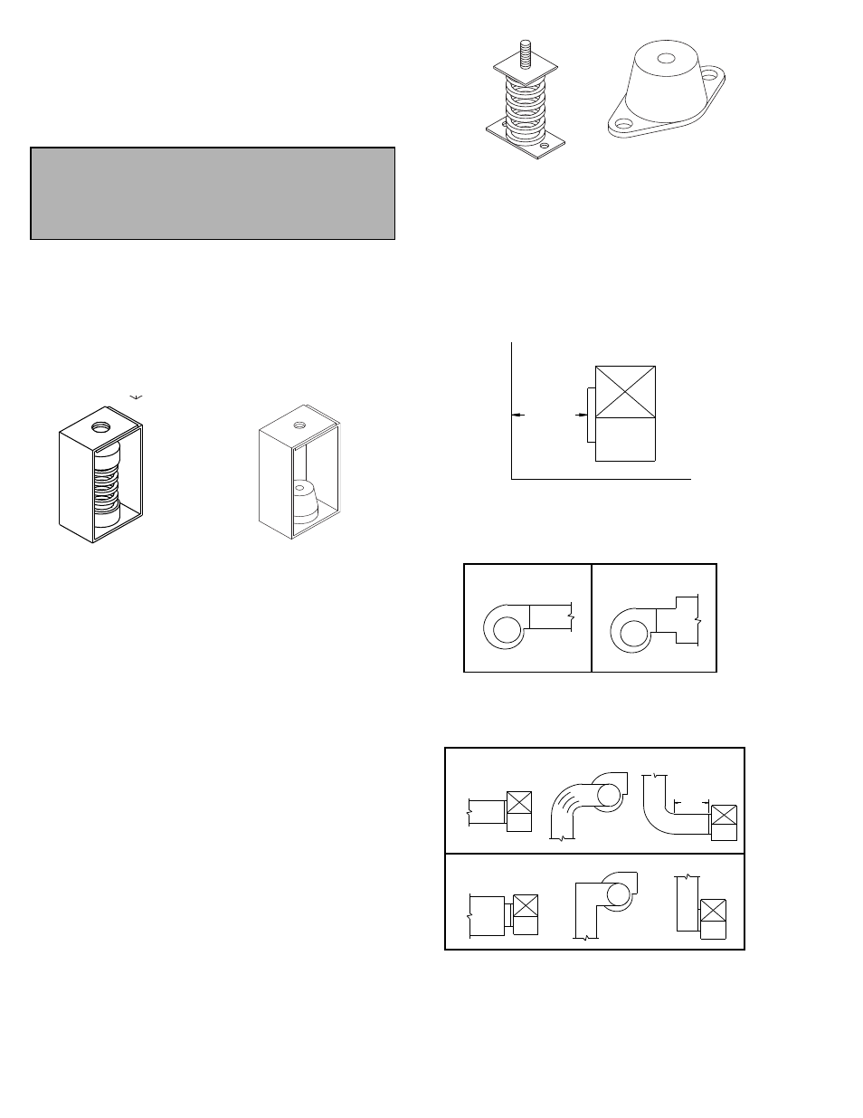
Non-Ducted Inlet Clearance
If your fan has an open inlet (no duct work), the fan must
be placed 1 fan wheel diameter away from walls and bulk-
heads. An inlet bell should be used in this case.
Free Discharge
Avoid a free discharge into the plenum. This will result in
lost efficiency because it doesn’t allow for a static regain.
Inlet Duct Turns
For ducted inlets, allow at least 3 fan wheel diameters
between duct turns or elbows and the fan inlet.
Discharge Duct Turns
Make sure that duct turns located near the fan discharge
curve in the direction of the fan’s rotation. Refer to the Dis-
charge Duct Turns illustration on page 3.
Figure 2 -Floor Mount Isolators
Rubber-In-Shear Isolator
Spring Isolator
Non-ducted Inlet Clearance
MIN 1 DIA
Correct
Incorrect
Free Discharge
Correct
Incorrect
Inlet Duct Turns
MIN 3
DIA
distortion which can lead to excessive belt and bearing
wear; its perimeter should contain all base angles and
rotating parts. Arrangement 10 fans above size 270 require
isolation rails. Please consult factory for isolation of
arrangement 9 fans due to the potential of uneven loading
caused by the motor and drives. Isolators should be
located between the fan system and the support structure.
Ceiling Mounted Isolators
Some applications require fan systems, designed for
floor mounting, suspended from ceiling supports. In such
cases, IMH fans of all arrangements should be installed on
either rails or bases in the classical orientation. Typically,
these systems are hung from the corners by rods, which
include isolation hangers of either spring or rubber-in-shear
design. Under no circumstances is the fan to be
inverted and hung by its base angles.
Floor Mounted Spring Isolators
a. Mount fan and motor on isolation base (if supplied).
b. Elevate fan (or isolation base) to operating height and
insert blocks to hold in position.
c. Position isolators under the fan (or isolation base) and
vertically align by inserting leveling bolt through
mounting holes in the fan or the base. The isolator
must be installed on a level surface.
d. Adjust the isolators by turning the leveling nut counter
clockwise several turns at a time alternately on each
isolator until the fan weight is transferred onto the iso-
lators and the fan raises uniformly off the blocks. Then
remove the blocks.
e. Turn lock nut onto leveling bolt and secure firmly in
place against the top of the mounting flange or frame.
f. Secure isolators to mounting surface.
Floor Mounted Rubber-In-Shear (RIS) Isolators
a. Mount fan and motor on an isolation base (if supplied).
b. Elevate fan to provide room to insert isolators
between the fan and foundation and block in position.
c. Position isolators under fan and secure bolts.
d. Remove blocks and allow fan to rest on floor. Isolators
must be installed on a level surface (leveling should
not be required).
e. Secure isolators to mounting surface.
Note
Although a certain amount of vibration is inherent in
operating centrifugal fans, extreme vibration is a seri-
ous problem that may cause structural and mechani-
cal failure.
Ceiling Mounted Spring Isolator
Rubber-in-Shear Ceiling Isolator
Figure 1- Ceiling Mount Isolators