COOK ERV User Manual
Page 8
8
Mounting
Foundation Mounting for Arrangement H
The ERV requires a
strong, level foundation
of reinforced poured
concrete. A correctly
designed concrete
foundation provides the
best means for mount-
ing floor units. The size
of the foundation is
determined by unit size
and the specific location
of the installation. The
use of rubber isolation
pads between the unit
base and the foundation
is recommended.
Use the following
guidelines to calculate
foundation size:
• The overall dimen-
sions of the foundation
should extend at least
six inches beyond the
outline of the unit.
• The weight of the
foundation should be
two to three times the
weight of the unit and its
motor.
Rail Mounting
Use the following recom-
mendations when
designing for rail mount-
ing:
• Rails should be posi-
tioned six to twelve
inches in from sides of
the unit.
• Rails should extend a
minimum of six inches
beyond the sides of the
unit.
Ductwork Connections
Discharge Duct Turns
Where possible, allow 3 duct diameters between duct turns
or elbows and the fan outlet. Refer to the figure below.
Free Discharge
Avoid a free discharge into the plenum. This will result in
lost efficiency because it doesn’t allow for a static regain.
Refer to figure below.
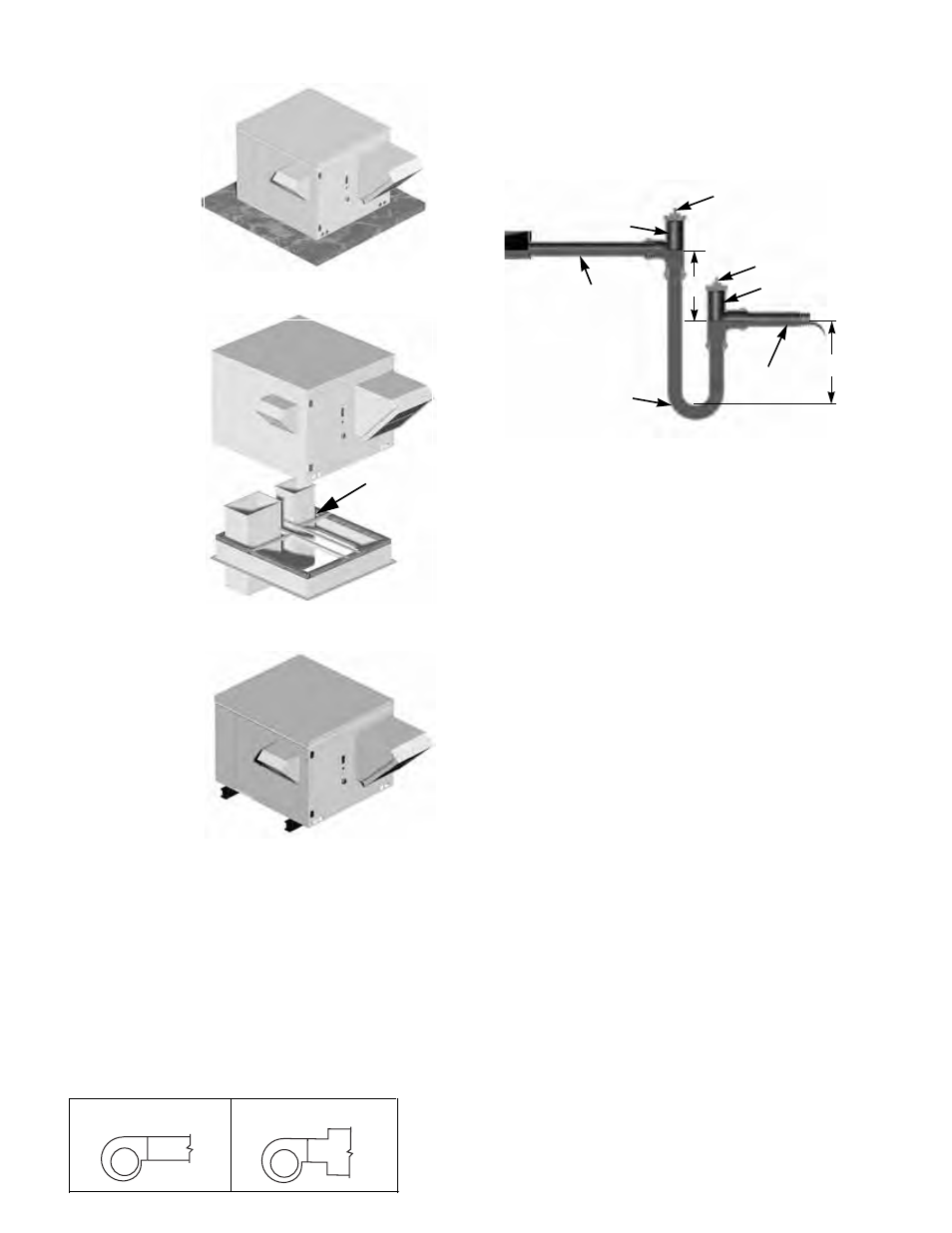
Installation of Condensate Drain Pan Traps
All drain and trap piping should be sized to match the con-
densate drain pan pipe connection supplied on cooling coil
equipped ERV’s. The below figure shows the correct lay-
out of a low maintenance, trouble-free condensate drain
pan trap. Finger tight plugs allow easy access for inspec-
tion and cleaning. To prevent an air leak into the unit
through the trap, dimensions “A” and “B” should be double
the total static pressure “head” found in the drain pan com-
partment.
Motor Installation
To prevent damage to the unit during shipping, extremely
heavy motors (cast iron or severe duty) are shipped loose
and must be field mounted by bolting the motor on the
motor mounting plate in the existing mounting slots.
The motor has been prewired to turn the proper direction.
Follow the directions on the motor schematic accompany-
ing the motor. Some motors can accommodate either 220V
or 440V operation. Once the motors are wired, test run the
ERV and check for proper rotation.
Wiring Installation
All wiring should be in accordance with local ordinances
and the National Electrical Code, NFPA 70. Ensure the
power supply (voltage, frequency, and current carrying
capacity of wires) is in accordance with the motor name-
plate.
Lock off all power sources before unit is wired to
power source.
Leave enough slack in the wiring to allow for motor
movement when adjusting belt tension. Some fractional
motors have to be removed in order to make the connec-
tion with the terminal box at the end of the motor. To
remove motor, remove bolts securing motor base to power
assembly. Do not remove motor mounting bolts.
Follow the wiring diagram in the disconnect switch
and the wiring diagram provided with the motor. Cor-
rectly label the circuit on the main power box and
always identify a closed switch to promote safety (i.e.,
red tape over a closed switch).
Do not allow the fan to run in the wrong direction.
This will overheat the motor and cause serious dam-
age. For 3-phase motors, if the fan is running in the
wrong direction, check the control switch. It is possi-
ble to interchange two leads at this location so that the
fan is operating in the correct direction.
Clean Out
ERV Condensate
Drain Pipe
Finger-Tight Plug
Finger-Tight Plug
Clean Out
Slope To Drain
(6” Min)
B
(6” Min)
A
Drain Trap
Curb Mounting
Ductwork
Mounting
Rails
Rail Mounting
Foundation Mounting for Arr. H
Correct
Incorrect