Final installation, Operation, Maintenance – COOK Economizer Fan User Manual
Page 4: Start-up, Inspection, Final installation steps, Modes
light will begin to flash. If the mode light is allowed to flash
for the full 3 seconds, the light will then stay on and the fan
will start.
If the panel contains a temperature controller, this mod-
ule will be powered only during mix mode. The display on
the temperature controller indicates the outlet temperature
of the fan and the set value which it is trying to produce by
mixing outside air and inside air. The set value temperature
must be between the indoor and outdoor temperatures in
order for the fan to match the set value. Refer to the Control
Panel for programming instructions to set the value temper-
ature.
If the operating mode is changed, such that the direction
of the propeller rotation must change, there will be a 30
second spin down delay before the start of the new mode.
Start-Up
Turn fan on in supply mode. Inspect for the following:
• Direction of rotation.
• Excessive vibration.
• Unusual noise.
• Improper motor amperage or voltage.
If a problem is discovered, immediately shut the fan
off. Lock out all electrical power and check for the
cause of the trouble. Refer to
Troubleshooting,
page 5
.
Inspection
Inspection of the fan should be conducted at the first
30
minute, 8 hour
and
24 hour
intervals of satisfactory opera-
tion. During the inspections, stop the fan and inspect as
instructed.
30 Minute Interval
Inspect bolts, setscrews, and motor mounting bolts.
Adjust and tighten as necessary.
8 Hour Interval
Inspect bolts, setscrews, and motor mounting bolts.
Adjust and tighten as necessary.
24 Hour Interval
Inspect bolts, setscrews, and motor mounting bolts.
Adjust and tighten as necessary.
Maintenance
Establish a schedule for inspecting all rotating parts. The
frequency of inspection depends on the operating condi-
tions and location of the fan.
Inspect fans exhausting corrosive air within the first
month of operation.
Yearly inspections are recommended for fans exhausting
non-contaminated air.
It is recommended that inspection of the unit be con-
ducted twice annually.
• Inspect bolts and setscrews for tightness. Tighten as
necessary. Refer to
Torque chart
.
• Inspect for cleanliness. Clean exterior surfaces only.
Removing dust and grease build-up on motor housing
assures proper motor cooling.
Final Installation Steps
a. Check and tighten fasteners and setscrews, particu-
larly unit mounting fasteners. Tighten according to the
recommended torque shown in table
Recommended
Torque for Setscrews/Bolts
..
b. Check for correct voltage with voltmeter.
c. Ensure all accessories are installed.
Operation
Pre-Start Checks
a. Lock out all the primary and secondary power sources.
b. Check and tighten fasteners and setscrews, particu-
larly those used for mounting the unit.
c. Check motor wiring.
d. Rotate the prop to ensure it does not rub against the
venturi.
e. Ensure fan and ductwork are clean and free of debris.
f. Close and secure all access doors.
g. Restore power to unit.
There are four basic designs for the operation control
panel on this unit. They are defined by whether or not the
fan unit is reversible, and whether or not the mix mode is
supplied with a temperature control and modulating damp-
ers.
Modes
MRS-D
- mix, recirculate, supply.
MRS-D with Modulating Temperature Controller
- mix
dependent upon fan outlet temperature, recirculate, supply.
MRSE-D
- mix, recirculate, supply, exhaust.
MRSE-D with Modulating Temperature Controller
-
mix dependent upon fan outlet temperature, recirculate,
supply, exhaust.
The function pad on the front of the control panel con-
tains two operators - a
Start/Mode
button and a
Stop
but-
ton.
When the Start/Mode button is depressed, the top mode
light will start to flash. This light will flash for 3 seconds to
indicate that a mode is ready to begin. If the mode button is
pressed again within the 3 second delay, the next mode
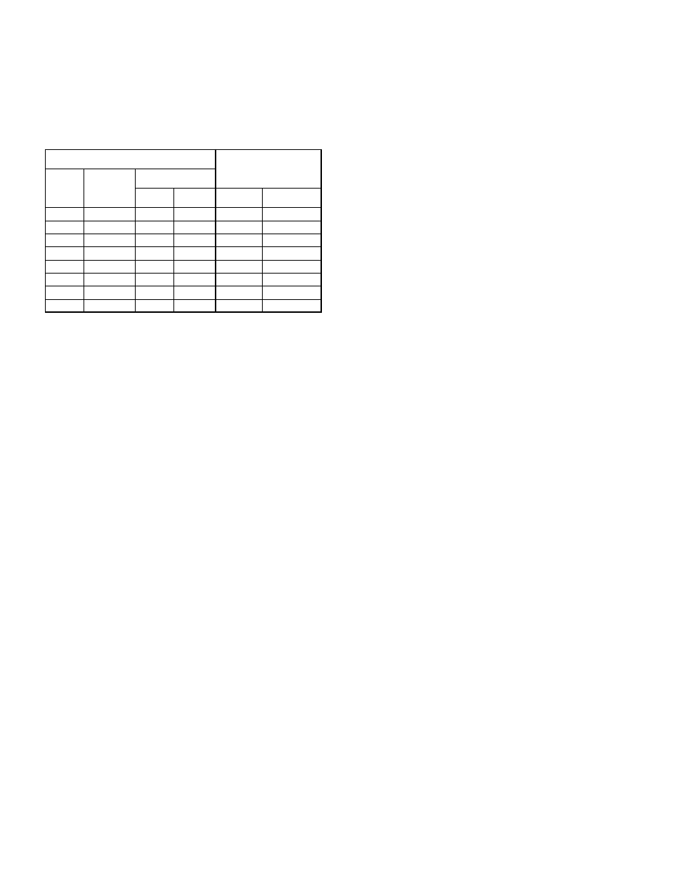
Recommended Torque for Setscrews/Bolts
Setscrews
Hold Down Bolts
Size
Key Hex
Across
Flats
Recommended
Torque
Min.
Max.
Size
Wrench
Torque
No.10
3/32”
28
33
3/8”-16
240
1/4”
1/8”
66
80
1/2”-13
600
5/16”
5/32”
126
156
5/8”-11
1200
3/8”
3/16”
228
275
3/4”-10
2100
7/16”
7/32”
348
384
7/8”-9
2040
1/2”
1/4”
504
600
1”-8
3000
5/8”
5/16”
1104
1200
1-1/8”-7
4200
3/4”
3/8”
1440
1800
1-1/4”-7
6000
4