Hood, Control panel, Temperature sensor – COOK Economizer Fan User Manual
Page 2: Hood assembly, Control panel installation, Temperature sensor installation
h. If no outlet diffuser is supplied, install the outlet guard
over the bottom of the cabinet assembly. Secure the
outlet guard to the cabinet with number 12 sheet metal
screws installed through the flange, spaced at 6 inch
intervals around the perimeter.
i. Install the control panel, if equipped, in a convenient
location. Refer to the wiring installation section, page 3
for wiring instructions.
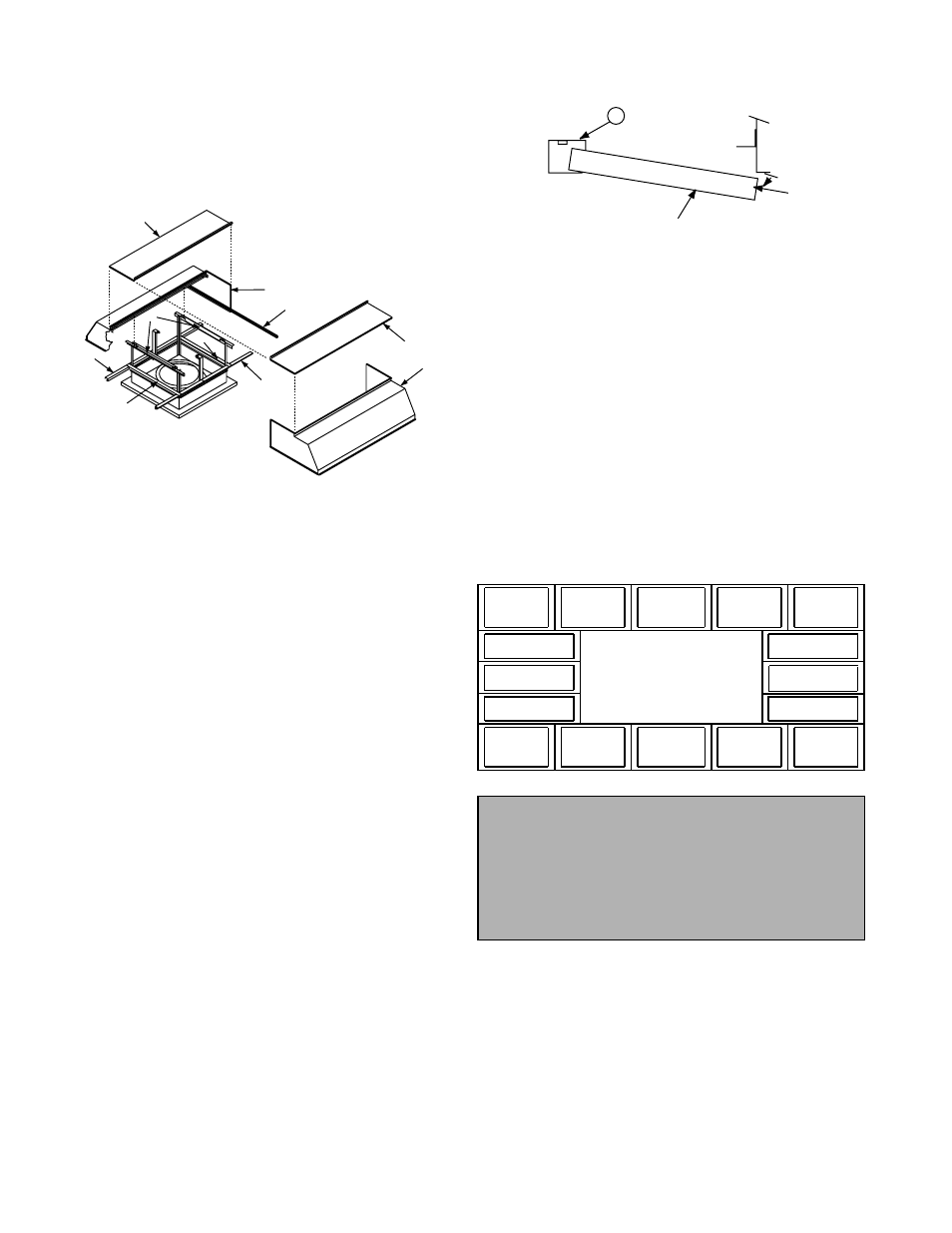
Hood Assembly
Hoods on some non-filtered units (size 54 or larger) and
some filtered units (size 48 or larger) require field assembly.
Assembly is accomplished using 1/2 inch and 9/16 inch
socket wrenches. Line-up punches and hand clamps will
speed up the assembly. Figure 1 shows the components
used to assemble the hood.
a. Place the hood halves (A) onto the hood supports (D).
Line up the hood flanges and bolt the flanges of the
hood ends together. The topcaps (B) must be inter-
locked for the flanges to meet correctly.
b. Go under the hood and bolt the hood (angle flange) to
the hood supports (D) at the four overlapping locations.
c. Install the two perimeter angles (C) inside each end of
the hood.
d. If there is a gap between the top cap edges, loosen the
top cap bolts. Install a bolt in each end of the top cap
flange to pull the two top caps together. Tighten the top
cap bolts.
Filtered Units Only
e. Place the two long filter retainers (E) and the two short
filter retainers (F) on top of the base and bolt the pieces
together.
f. Bolt the long filter retainers (E) to the perimeter angles
(C) that are at the ends of each hood.
g. Install filters according to the Filter Schedule. Insert the
edge of the filter into the filter retainer (E), swing filter
A
B
E
F
D
C
A
B
E
F
Figure 1
into position and flip the filter holding the clip into posi-
tion. Refer to the Filter Installation Detail illustration.
Control Panel Installation
(if equipped)
The optional control panel is used to control the functions
of the Economizer fan. Locate the panel in a convenient
area to install wiring and operate the fan. Permanently
attach the control panel to a suitable structure by bolting
through the back of the panel.
Temperature Sensor Installation
(if equipped)
A temperature sensor is supplied as a part of the optional
Modulating Temperature Control. To prevent damage to the
fan during transit, the temperature sensor is shipped loose
(inside the control panel). Follow the instructions below to
mount the temperature sensor.
a. Drill a 11/32 inch diameter hole in one corner of the
venturi panel, located in the bottom of the fan cabinet.
b. From the inside of the cabinet, screw the compression
fitting (shipped with the sensor) into the hole.
c. Install the sensor through the hole (push through 1/2”).
d. Tighten the fitting to hold the sensor in place.
Follow the wiring diagram in the disconnect switch
and the wiring diagram provided with the motor.
E
Economizer Fan Filter Installation Detail
Type 1
Type 1
Type 1
Type 1
Type 1
Type 1
Type 2
Type 2
Type 2
Type 2
Type 2
Type 2
Type 2
Type 2
Type 2
Type 2
Economizer Fan
Filter Schedule
Personal Safety
Disconnect switches are recommended. Place
the disconnect switch near the fan in order that
the power can be swiftly cut off in case of an
emergency, and in order that maintenance per-
sonnel are provided complete control of the
power source.
2