Swiftech MCX462+T User Manual
Page 2
Copyright Swiftech 2002 – All rights reserved – Last revision date: Sep 11, 2002
Rouchon Industries, Inc., dba Swiftech – 1703 E. 28
th
Street, Signal Hill, CA 90755 – Tel. 562-595-8009 – Fax 562-595-8769
E Mail: Swiftech @swiftnets.com – URL:
http://www.swiftnets.com
Information subject to change without notice
Page 2
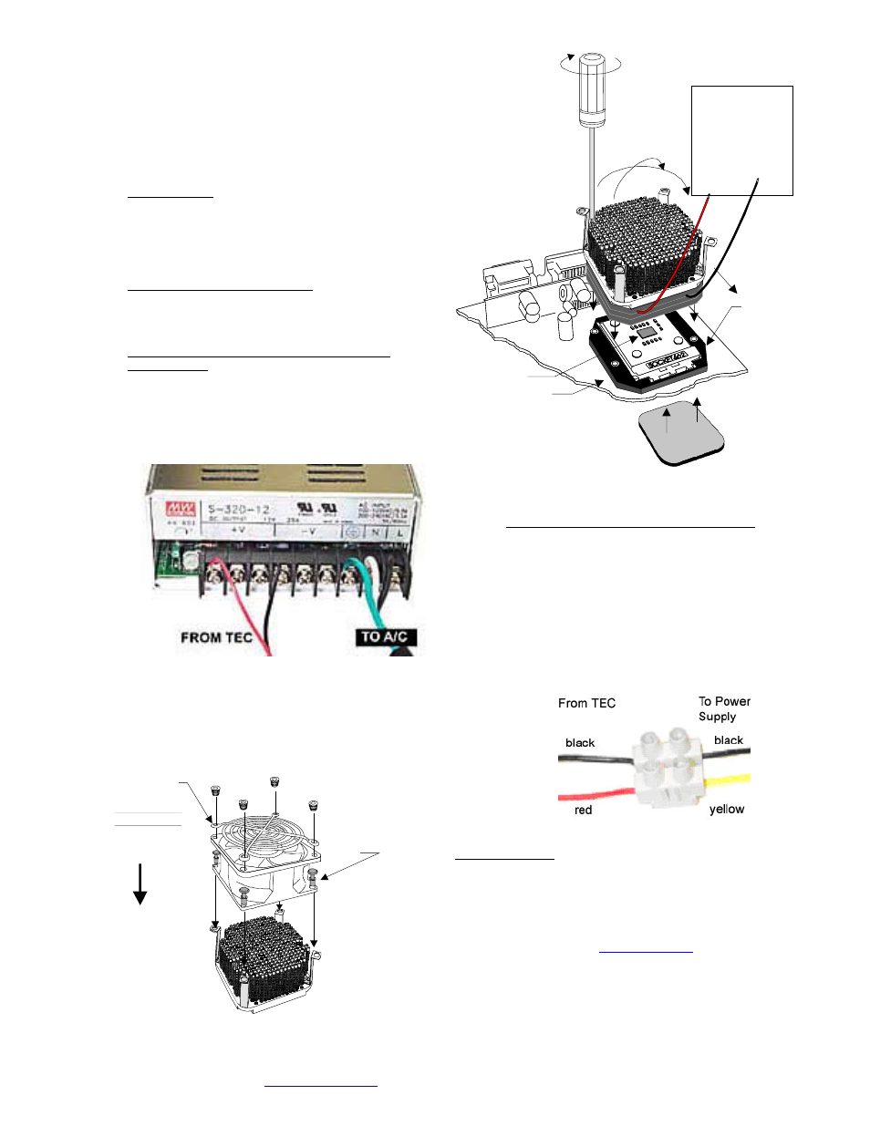
1.
The case should be laying flat on a table.Install the
MCX462+T
heatsink onto the CPU as shown in fig. 2,
heatsink step side over the socket’s cam box. Tighten the
mounting screws in a crisscross pattern. Important note: Due
to wide variations in gasket thickness tolerances, we
suggest that you uninstall the heatsink once following the initial
assembly, just to verify that you have good contact between
cold plate and CPU. Inspect the grease imprint that the CPU
left on the copper plate: it should be perfectly even!
2.
Fan installation:
!
Use provided snap-rivets as shown in fig. 4 to secure fan to
heatsink.
!
Recommended fans
Minimum 68cfm 80mm fans, such as but not limited to Delta
FFB0812SHE, FFB0812EHE, or Vantec 84cfm Tornado.
3.
Thermoelectric module installation:
!
IMPORTANT WARNING: Solder joints of the wires to the
thermoelectric module are extremely fragile. Bending the wires
at their root will break the solder joint, with no possible repair.
Swiftech will not honor the warranty for broken wires.
!
Connection to a dedicated auxiliary power supply
(recommended):
#
The TEC module is provided with “bare wires” to facilitate
installation with screw type terminals. We recommend the
“Meanwell S320-12” power supply, available on our website
in the liquid cooling accessories section. Connect red wire
from TEC module to the +V terminal, and black wire to the
–V terminal as shown in figure 3 below:
Figure 3
#
Minimum requirements for a dedicated power supply: 20A
@ +12 V.
#
If adjustable voltage is available: setting the voltage higher
than +12V is not recommended. Lower voltage, can be
safely used, down to 9 volts.
Fan guard
and fan sold
Separately
Direction of
the fan flow
(fan label
facing down)
Provided
Snap rivets
here
Figure 4
CPU core
Crisscros
tightening
pattern
Step side
This way
over
cam box
Connect
Red wire
to +12 VDC
TO POWER
SUPPLY
(min 20A at 12V)
Connect
black wire
to - VDC
Neoprene sticker
to back of MB
MB gasket
Figure 2
!
Connection to an ATX computer power supply:
#
Important Warning: to connect the MCX462+T cooler
to your computer power supply, you must carefully
consider the existing requirements of other devices
connected on the +12V line. Connecting to an
underpowered unit will definitely damage the power
supply.
#
Minimum requirements for an ATX computer power
supply: 28A at +12V in a typical setup.
#
Only use the provided euro-style wire connector
shown in fig 4 below. Connect red wire from TEC
module to +12V of P/S (Yellow wire), and black wire to
black wire:
Figure 5
III. Final inspection
Now that the heat sink is installed, startup your computer, go into the
BIOS and observe the CPU temperature. Under normal ambient
temperature conditions, the processor temperature should never
exceed 55
°
C (130
°
F). If it does, shut down the computer
immediately, and review your entire installation. Troubleshooting help
is available on our web site at
www.swiftnets.com
, or by calling
customer support at 562-595-8009.
DISCLAIMER: Swiftech assumes no liability whatsoever,
expressed or implied, for the use of these products.