Swiftech MCX462+T User Manual
Swiftech Computer Accessories
Copyright Swiftech 2002 – All rights reserved – Last revision date: Sep 11, 2002
Rouchon Industries, Inc., dba Swiftech – 1703 E. 28
th
Street, Signal Hill, CA 90755 – Tel. 562-595-8009 – Fax 562-595-8769
E Mail: Swiftech @swiftnets.com – URL:
http://www.swiftnets.com
Information subject to change without notice
Page 1
Packing list
Parts Qty
Parts
Qty
Thermoelectric Heat Sink assembly
1
6-32 Hex Lock-Nuts (for
motherboard)
4
Snap-rivets (for 80mm fan)
4
Black fiber washers (for
motherboard)
10
Spring assembly – pre-installed
4
2 pole euro-style wire
connector
1
Standoffs
4
Thermal grease – Arctic
Alumina
1
.220x.046 Nylon spacers (for motherboard)
4
Motherboard gaskets
2
Preamble:
This product is intended for expert users only. Please consult with a qualified technician for installation. Improper installation may result in damage
to your components.
Swiftech assumes no liability whatsoever, expressed or implied, for the use of these products, nor
their installation.
The following instructions are subject to change without notice. Please visit our web site at
www.swiftnets.com
for updates.
I. Preparing the motherboard
1.
You must uninstall your MB prior to installing the MCX462+
heat sink.
2.
Install standoffs in MB
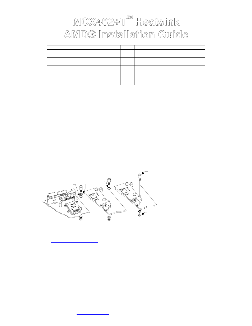
Determine which standoff washers to use, depending on the mounting holes sizes of your particular MB model:
•
Large holes .230”(5.8mm) diameter, use in the following order: standoff, black fiber washer, .220x.046 Nylon spacers (fits inside the
MB hole), then on the other side of the MB, black fiber washer, and lock-nut.
•
Small grounded holes .150”(3.8mm) diameter (you can recognize grounding by a silver ring around the holes), use in the following
order: standoff directly to the MB (black fiber washer is NOT necessary), then on the other side of the MB, black fiber washer, and lock-
nut.
•
Small holes, NOT grounded (bare circuit board): you must use black fiber washers, or damage to the MB may occur: use in the
following order: standoff, black fiber washer, then on the other side of the MB, black fiber washer, and lock-nut.
MB with
large holes
MB with
small non-grounded
holes
must use
fiber washer
MB with
small grounded
holes, no washer
necessary on
this side
Use .220x.046
nylon spacer
(fit inside the hole)
Standoff
Hex lock-nut
to back side of
the MB
Figure 1
Install standoff in each one of the
four holes surrounding the socket.
Keep the standoff & washer centered
over the MB holes, and secure with
hex lock nuts on backside of the MB.
•
Fill-up the socket with dielectric grease: Do not confuse dielectric grease with the provided thermal compound that is only used for
the CPU. Dielectric grease is used to prevent condensation where parts are exposed to cold. We use Luberex (available on our web site
under the
liquid cooling accessories section
), but any similar product can be used, as long as it clearly states “good dielectric properties”.
Fill-up the socket center cavity (grease is to be level with the upper surface of the socket), and coat the socket pinholes with grease.
Spread the grease with your finger so that it will penetrate inside the pinholes.
•
Insert the processor into the socket. Since there is grease inside the socket, some hydraulic pressure lift may occur: for this reason,
make sure that the processor is completely inserted into the socket. Apply paper-thin coat of thermal compound to processor core,
using a razor blade, or a credit card, held between thumb and index at a 45
°
angle. It is critical to ascertain that the entire core is covered
with a uniform coat of thermal compound. Thermal performance will dramatically decrease if any portion of the core is not covered by
thermal compound.
•
Remove the peel-off paper back of the motherboard gasket, and install it as shown Fig. 2, sticky side towards the motherboard.
•
Apply the provided neoprene sticker to the back of the motherboard as shown in Fig. 2
3.
Install the MB inside the case..
II. Heat sink Installation