Swiftech H20 8501 2003 User Manual
Page 3
The following is a typical sequence of components installation. Placement of the cooling components may vary depending on your case configuration.
1.
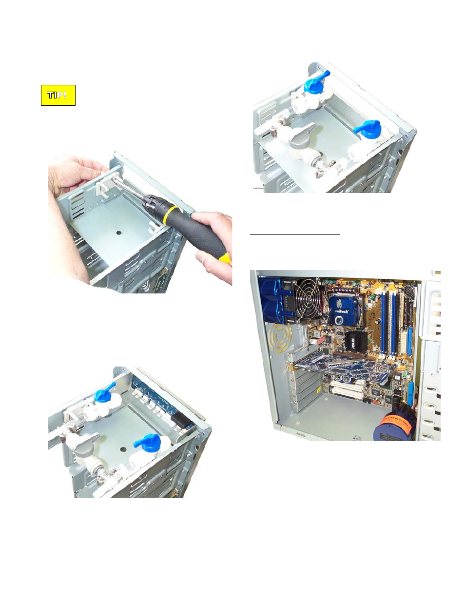
FBK525 Fill & Bleed installation
The fill-and-bleed kit may be installed pretty much anywhere in
the chassis, thanks to its flexible retention clip attachment system.
A majority of users will find it convenient to install in a 5 ¼” bay.
To simplify the bleeding process described in
following chapters, the fill-and-bleed kit should
preferably be installed at the highest point of the
cooling circuit, such as the uppermost 5 ¼” drive
bay.
Each clip will be attached to the chassis with the provided screws
as shown in the example in Figure 1 below. A single screw is
sufficient per clip.
Figure 1
The clip retention system accommodates a wide range of
configurations, which will depend on the particular chassis, and
users needs. For example, a rheobus can easily be installed in
the same bay as the FBK525 as shown Figure 2 below: Another
example in Figure 3 shows a “standard” setup.
Figure 2
Notice how each valve is only held by one set of jaws in this
example
Figure 3
A “standard” setup
2.
MCR80-F1 Radiator installation
The radiator/fan assembly fits into any exhaust opening designed
to receive a 80mm case fan. Depending on the case design, the
assembly will either fit straight up (inlet and outlet up), or may need
to be rotated 90
° as shown in Figure 4 Below:
Figure 4
Please use the separate installation guide provided with the MCR80-
F1 radiator assembly to fasten the radiator to the chassis. If space
permits, a second radiator can also be installed in parallel to the first
one (see Figure 7).
TIP!
Rouchon Industries, Inc., dbA Swiftech – 1703 E. 28
th
St, signal Hill, CA 90755, USA – T (562) 595-8009 – F (562) 595-8769 – All content Copyright
Swiftech 2004 – Last edited 1-24-04– Subject to revision without notice
- 3 -