Installation – Blodgett SBC-G Series User Manual
Page 8
6
OM-SBC-G
Installation
WARNING
DO NOT CONNECT THE DRAIN DIRECTLY
TO A BUILDING DRAIN. BLOCKING THE
DRAIN IS HAZARDOUS.
CAUTION
DO NOT USE PLASTIC PIPE. DRAIN MUST BE
RATED FOR BOILING WATER.
IMPORTANT
DO NOT ALLOW WATER TRAPS IN THE LINE.
A TRAP CAN CAUSE PRESSURE BUILD-UP IN
THE CAVITY, WHICH MAY CAUSE THE DOOR
GASKET TO LEAK.
For a Unit on casters:
a. The installation shall be made with a connector that complies with the
standard for connectors for movable gas appliances; ANSI Z21.69.CSA
6.16, and a quickdisconnect device that complies with the standard for
quick-disconnect devices for use with gas fuel, ANSI Z21.41.CSA 6.9.
b. Adequate means must be provided to limit the movement of the appliance
without depending on the connector and the quick disconnect device or its
associated piping to limit the appliance movement.
c. The location where the restraining device may be attached to the appliance
shall be in accordance with specifications for the device.
3. Water Connection(s)
Install a check valve to prevent back flow in the incoming cold water line, as
required by local plumbing codes. Water pressure in the line should be between
30 and 60 PSI. If pressure is above 60 PSI, a pressure regulator will be needed.
These pressures must provide the 1.5 gallons per minute required for proper
steamer function.
A 3/4 inch female NH connector (garden hose type) is used to attach the water
supply to the inlet valve. Minimum inside diameter of the water feed line is 1/2
inch. Use a washer in the hose connection. Do not allow the connection to leak,
no matter how slowly. Do not over-tighten hose connections.
This equipment is to be installed to comply with the basic plumbing code of the
Building Officials and Code Administrators International, Inc. (BOCA) and the Food
Service Sanitation Manual of the Food and Drug Administration (FDA).
NOTE: Local code may also require check valves in the water supply line.
4. Drain Connection
Level the steamer front to back, and pitch it slightly to the rear (maximum 1/4
inch) by adjusting the optional legs or the bullet feet on the optional stand.
There must be a free air gap between the end of the hose and the building drain.
The free air gap should be as close as possible to the unit drain. There must also
be no other elbows or restrictions between the unit drain and the free air gap.
Install the drain line with a constant downward pitch.
Proper Drain Line Connection –– Drain Line must have a constant downward
pitch of at least 1/4” per foot. Observe local code regarding air gap spacing and
drain connections.
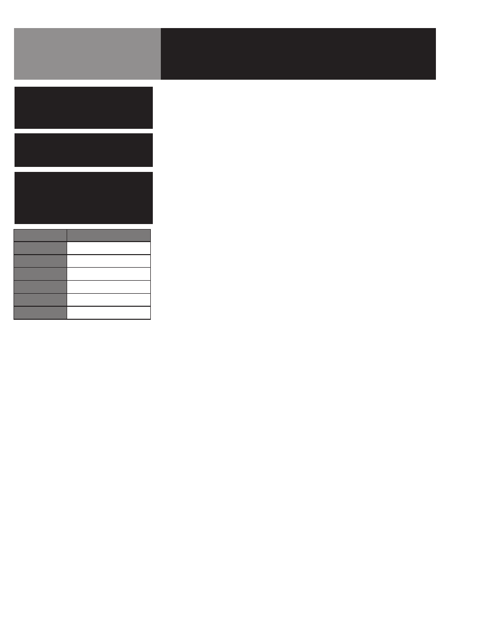
Steamer Type
NPT Pipe Size Required
3-Pan
1.5"
(2) 3-Pan
2.5"
5-Pan
1.5"
(2) 5-Pan
2.5"
10-Pan
2.0”
(2) 10-Pan
2.0"