Straight-through wiring, Table 3: straight-through rj45 pin assignments, 1 (tx+) – Allied Telesis AT-MR820T User Manual
Page 51: 2 (tx-), 3 (rx+), 6 (rx-), Crossover wiring, Table 4: crossover rj45 pin assignments, Straight-through wiring crossover wiring
AT-MR420T and AT-MR820T Installation Guide
29
Each twisted-pair link segment must have a male connector attached
to both ends. According to the 10Base-T specification, pins 1 and 2 on
the connector are used for transmitting data; pins 3 and 6 are used for
receiving data.
Straight-through Wiring
If the twisted-pair link segment is to join two ports on a switch, and
only one of the ports has an internal crossover, the two pairs of wires
must be straight-through, as shown in Table 3. In Table 3, TX and TR
represent Transmitted Data and Ready Data respectively.
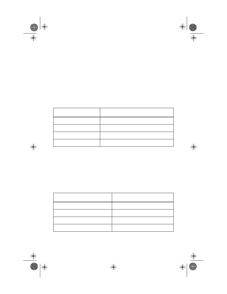
Table 3: Straight-through RJ45 Pin Assignments
Crossover Wiring
Two repeaters can communicate only if the transmitter on one unit is
connected to the receiver on the other unit. This reversal, or crossover
function, can be implemented either in the wiring or in the device itself.
When connecting repeaters, a crossover must be used in the wiring. See
Table 4 for crossover pin assignments.
Table 4: Crossover RJ45 Pin Assignments
Hub
Device
1 (TX+)
1 (TX+)
2 (TX-)
2 (TX-)
3 (RX+)
3 (RX+)
6 (RX-)
6 (RX-)
AT-MR420T/AT-MR820T
AT-MR420T/AT-MR820T
1 (TX+)
3 (RX+)
2 (TX-)
6 (RX-)
3 (RX+)
1 (TX+)
6 (RX-)
2 (TX-)
MRx20T(UTP)Ver6_Book Page 29 Thursday, April 3, 1997 5:18 PM