Table 1: hub status leds, System check, Check the link ok led on the front panel for th – Allied Telesis AT-MR820T User Manual
Page 32: After a successful connection, disconnect the a, Establish a connection from a device connected, Once the connection between devices attached to, If all ports test successfully, install the res, Technical support fax order
Installation
10
1
Occasional collisions are normal in Ethernet networks. A constantly lit Collision LED may indicate
that there is a port with excessive traffic problems. If the Collision LED is flashing steadily, and
you are using an external transceiver on the AUI backbone port, make certain that the SQE/
Heartbeat Test function is disabled. Repeaters will not function properly when the SQE/Heartbeat
Test is active. Continual flickering of the Collision LED also may indicate excessive frame
collisions on a segment. This may be caused by an overloaded segment or faulty cable or
connection.
System Check
1. Check the LINK OK LED on the front panel for the first 10Base-T
port that is connected. A steady green LED indicates continuity. A
valid network connection must be made from the connected port to
a host or workstation on another port.
2. After a successful connection, disconnect the active 10Base-T
connector and connect it to the next successive port. Continue this
process until all 10Base-T ports have been validated with good
network connections.
3. Establish a connection from a device connected to port 1 to a device
connected to port 2.
4. Once the connection between devices attached to ports 1 and 2 has
been successfully established, remove the RJ45 connector from port
2 and connect it to each of the subsequent AT-MR420T/AT-MR820T
10Base-T ports, 3 through 4/8, to verify their functions.
5. If all ports test successfully, install the rest of the 10Base-T RJ45
connections and ensure that the LINK OK LED for each port is
illuminated. Remember, the 10Base-T device on the opposite end of
the UTP cable must be operational.
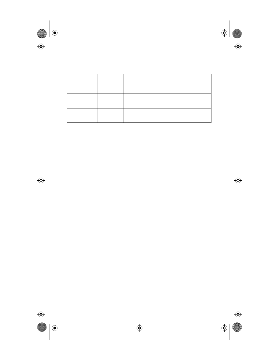
Table 1: Hub Status LEDS
LED
Color
Description
POWER
Green
Lights when power is applied
COLLISION
1
Amber
Flashes indicating an SQE or excessive frame
collisions
ACTIVITY
Green
Indicates that the repeater is functional and is
transmitting packets
MRx20T(UTP)Ver6_Book Page 10 Thursday, April 3, 1997 5:18 PM