Figure8: aui network port, 10base5 (thick) ethernet cable, Aui drop cables – Allied Telesis AT-MR820T User Manual
Page 38
Connectivity
16
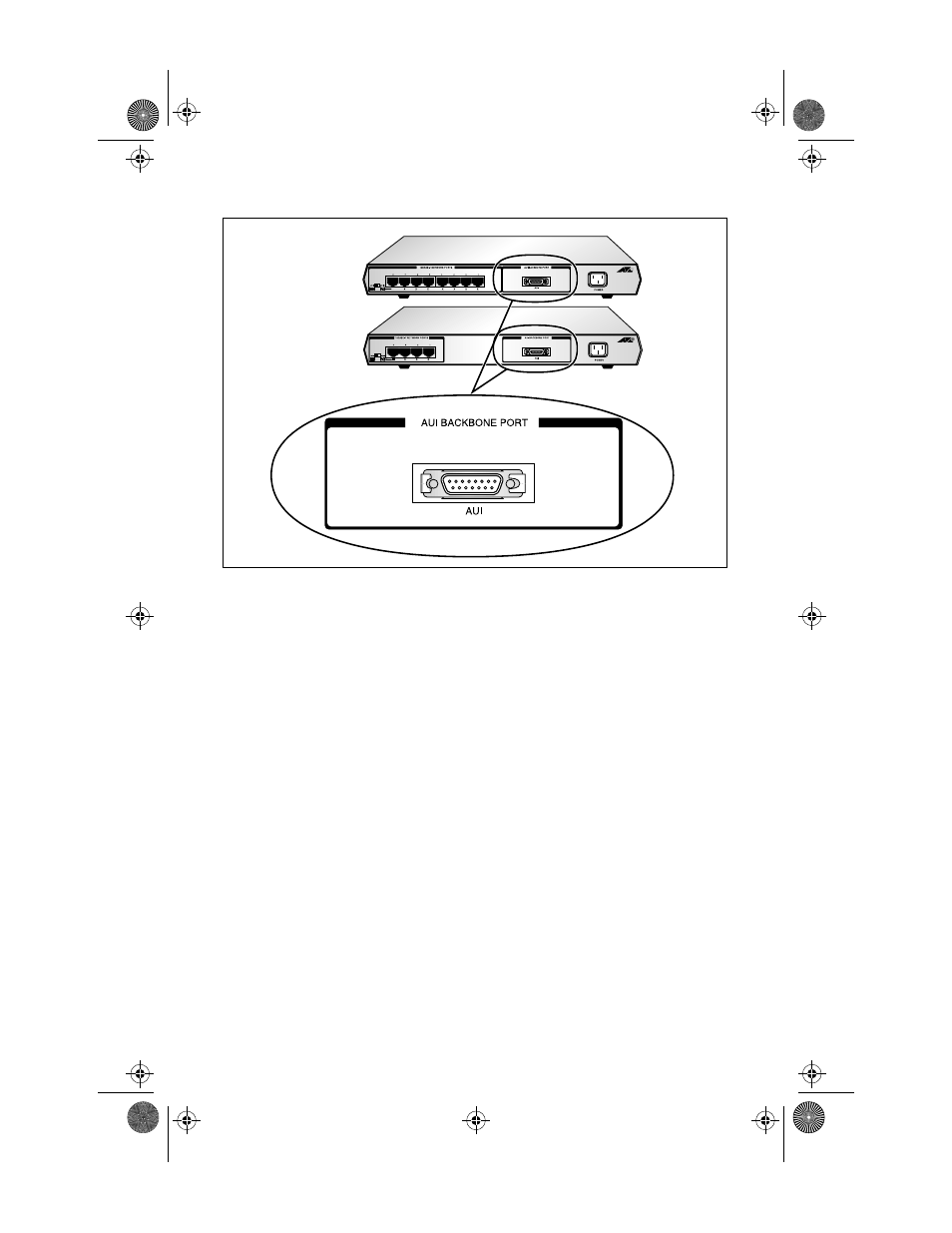
Figure 8: AUI Network Port
10Base5 (Thick) Ethernet Cable. When configuring 10Base5 coax
segments, IEEE 802.3 specifications allow a maximum of 100 MAU
attachments, spaced at multiples of 2.5 meters (8.2 feet) measured
accurately from the cable end (50
Ω
terminator included). The 10Base5
cable segment should not exceed 500 meters (1,640 feet). Worst-case
“end-to-end” propagation delay of a 10Base5 coax segment is 2165 ns.
Propagation delay of 10Base5 Ethernet coax is calculated at 4.33 ns/
meter. Both ends of the segment must be terminated with a 50
Ω
termination with a power rating of 0.5 watts or greater. Earth
grounding of the segment shield is allowed at only one point on the
cable.
AUI Drop Cables. AUI or drop cables should not exceed 50 meters (164
feet). Attachments may be made only to the cable ends at the 15-pin
D-shell connector. AUI cables may have a maximum 257 ns
propagation delay, as used for computing the worst-case propagation
delay of a cable system. AUI cable propagation delay is approximately
5.13 ns/meter. This cable internally consists of four shielded twisted
pair wires with an overall shield and drain wire; a 15-pin D-shell male
connector at one end and a 15-pin D-shell female connector at the other
end. Cable impedance is nominally 78
Ω
. The AUI cable typically
connects a transceiver attached to a coaxial segment to a DTE
(workstation).
MRx20T(UTP)Ver6_Book Page 16 Thursday, April 3, 1997 5:18 PM