Backbone networks, Figure12: at-mr420t backbone topology – Allied Telesis AT-MR820T User Manual
Page 43
AT-MR420T and AT-MR820T
21
Backbone Networks
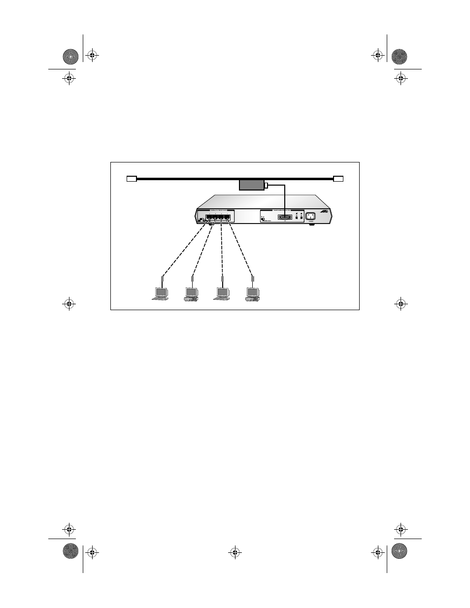
The most straightforward topology is a backbone network. Figure 12
show a backbone network topology with the AUI port attaching to a
coaxial Ethernet cable.
Figure 12: AT-MR420T Backbone Topology
In a backbone network topology, each workgroup has its own local
network and the backbone is used to link the various workgroups
through the bridges. The advantages of a backbone network topology
are twofold:
❑
When the backbone network is operating correctly, any
problem within a sub-network does not affect other sub-
networks.
❑
Since faults are isolated to a single sub-network, they are
easier to locate.
100 Meters
maximum
Category 3-5
UTP cable
wired
Pin to Pin
AUI cable
Coaxial Backbone
Ethernet
Transceiver
MRx20T(UTP)Ver6_Book Page 21 Thursday, April 3, 1997 5:18 PM