Diagnostic leds, Certification, 10base-t pin assignments – Allied Telesis AT-MR820T User Manual
Page 50: Connectors, Figure16: connector pin numbers, Diagnostic leds certification
Technical Specifications
28
Diagnostic LEDs
Individual port link status (4/8)
Individual port receive activity (4/8)
Hub status (3), specifying:
❑
Both Transmit and Receive activity
❑
Collision
❑
Power
Certification
Safety
UL 1950, CSA 22.2 No. 950 (Canadian
Standards Association), TUV EN60950
Emission
FCC Part 15 Class A, VCCI Class 1,
CDOC Class A, EN55022 (CISPR 22)
Class A
10Base-T Pin Assignments
An Ethernet twisted-pair link segment requires two pairs of wires.
Each wire pair is identified by solid and striped colored wires. For
example, one wire in the pair might be red and the other wire, red with
white stripes.
Connectors
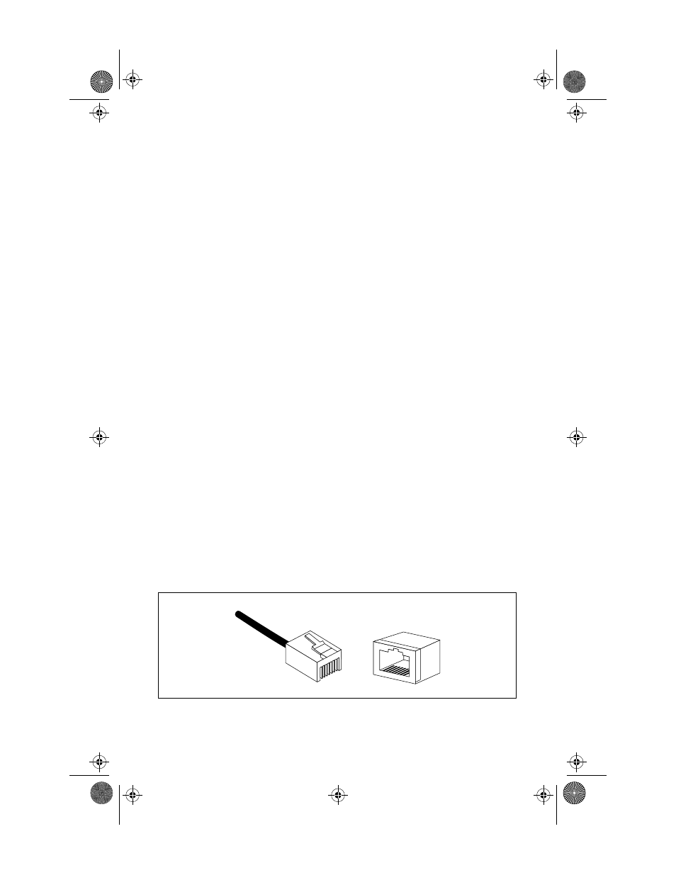
Referring to Figure 16, note how the pins are numbered. Be sure to
hold the connectors in the same orientation when connecting the wires
to the pins.
Figure 16: Connector Pin Numbers
1
8
8
1
MRx20T(UTP)Ver6_Book Page 28 Thursday, April 3, 1997 5:18 PM