Powering on an at-gs900/8e switch, Figure 18 – Allied Telesis AT-GS900/8E User Manual
Page 43
AT-GA900/8 and AT-GA900/8E Gigabit Ethernet Switches Installation Guide
43
Figure 18. Securing the Power Cord with the Retaining Clip
4. Plug the other end of the power cord into a wall outlet.
5. Verify that the POWER LED is green. If the LED is OFF, refer to
Chapter 3, “Troubleshooting” on page 45.
The switch is now powered on and ready for network operations.
Powering On an
AT-GS900/8E
Switch
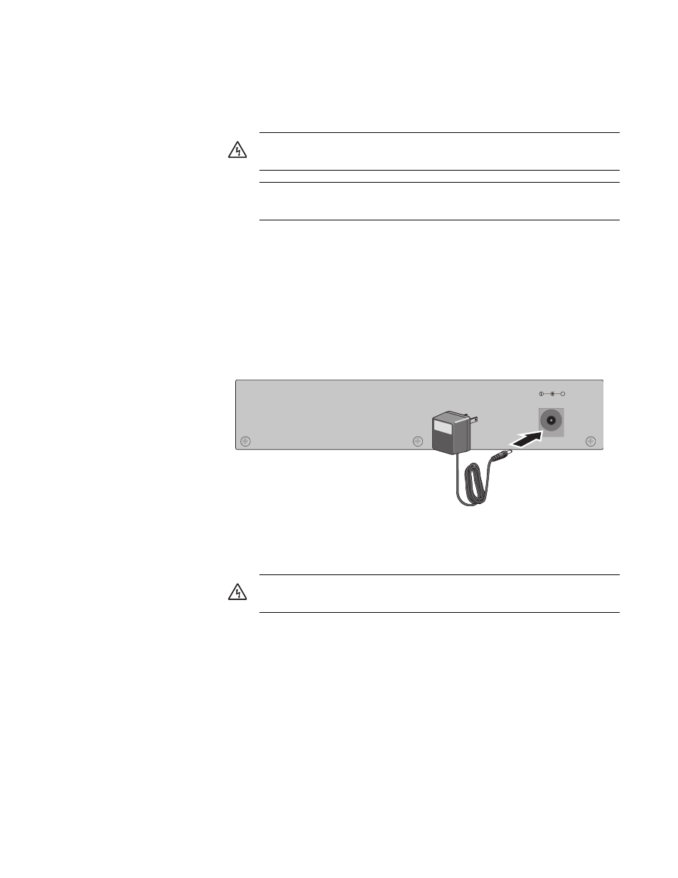
To power on an AT-GS900/8E switch, perform the following procedure:
1. Plug the power cord on the power adapter into the power connector on
the back panel of the AT-GS900/8E switch, as shown in Figure 19.
Figure 19. Connecting the Power Adapter
2. Plug the adapter into a power outlet.
3. Verify that the POWER LED is green. If the LED is OFF, refer to
Chapter 3, “Troubleshooting” on page 45.
The switch is now powered on and ready for network operations.
Warning: Power cord is used as a disconnection device. To de-
energize equipment, disconnect the power cord.
5
Pluggable Equipment. The socket outlet shall be installed near
the equipment and shall be easily accessible.
7
Warning: Power cord is used as a disconnection device. To de-
energize equipment, disconnect the power cord.
5
5-12V DC
+