Front and back panels, At-gs900/8, At-gs900/8e – Allied Telesis AT-GS900/8E User Manual
Page 17: Port leds
AT-GA900/8 and AT-GA900/8E Gigabit Ethernet Switches Installation Guide
17
Front and Back Panels
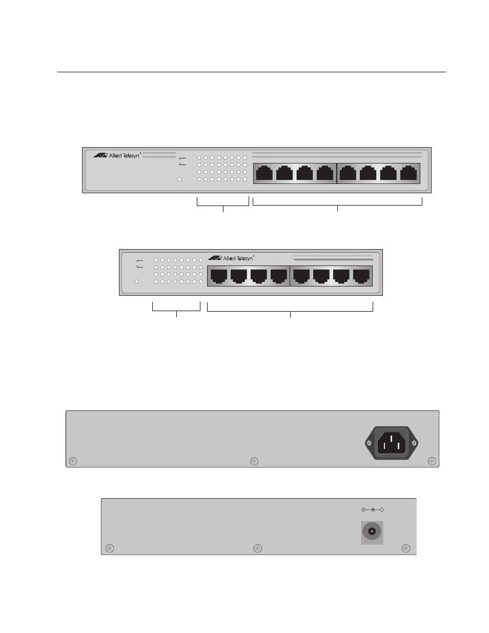
Figure 1 illustrates the front panels of the AT-GS900/8 and AT-GS900/8E
switches.
Figure 1. AT-GS900/8 and AT-GS900/8E Front Panels
Figure 2 illustrates the back panels of the AT-GS900/8 and AT-GS900/8E
switches.
Figure 2. AT-GS900/8 and AT-GS900/8E Back Panels
560
M
0
0
1
T
C
A
/
K
N
I
L
X
D
F
R
E
W
O
P
2
8
/
0
0
9
S
G
-
T
A
h
c
t
i
w
S
t
e
n
r
e
h
t
E
t
i
b
a
g
i
G
T
-
E
S
A
B
0
0
0
1
/
0
0
1
/
0
1
M
0
1
M
0
0
0
1
1
3
4
5
8
7
6
2
1
3
4
5
6
7
8
10/100/1000Base Twisted Pair Ports
Port LEDs
AT-GS900/8
561
M
0
0
1
T
C
A
/
K
N
I
L
X
D
F
R
E
W
O
P
2
E
8
/
0
0
9
S
G
-
T
A
h
c
t
i
w
S
t
e
n
r
e
h
t
E
t
i
b
a
g
i
G
T
-
E
S
A
B
0
0
0
1
/
0
0
1
/
0
1
M
0
1
M
0
0
0
1
1
3
4
5
8
7
6
2
1
3
4
5
6
7
8
10/100/1000Base Twisted Pair Ports
Port LEDs
AT-GS900/8E
100-240V~ 50-60Hz 0.6A
AT-GS900/8
5-12V DC
+
AT-GS900/8E
This manual is related to the following products: