Leds, Table 2. system and port led descriptions, At-gs900/8 – Allied Telesis AT-GS900/8E User Manual
Page 19: At-gs900/8e
AT-GA900/8 and AT-GA900/8E Gigabit Ethernet Switches Installation Guide
19
LEDs
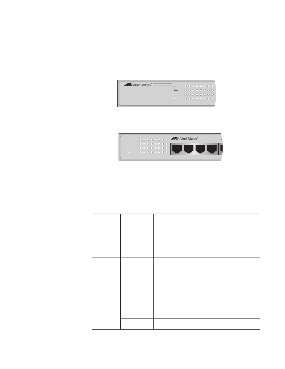
The LEDs on the front panel display the system and port status
information. Each port has four LEDs as shown in Figure 3.
Figure 3. AT-GS900/8 and AT-GS900/8E System and Port LEDs
Table 2 describes the AT-GS900/8 and AT-GS900/8E system and port
LEDs.
Table 2. System and Port LED Descriptions
LED
State
Description
POWER
Off
The switch is not receiving power.
On
The switch is receiving power.
10M
Solid Green
The port is operating at 10 Mbps.
100M
Solid Green
The port is operating at 100 Mbps.
10M and
100M
Solid Green
The port is operating at 1000 Mbps.
LINK/ACT Off
The port has not established a link with an
end node.
Blinking
Green
The port is transmitting or receiving data.
Green
A valid link has been established on the port.
562
M
0
0
1
T
C
A
/
K
N
I
L
X
D
F
R
E
W
O
P
2
8
/
0
0
9
S
G
-
T
A
h
c
t
i
w
S
t
e
n
r
e
h
t
E
t
i
b
a
g
i
G
T
-
E
S
A
B
0
0
0
1
/
0
0
1
/
0
1
M
0
1
M
0
0
0
1
1
3
4
5
8
7
6
AT-GS900/8
563
M
0
0
1
T
C
A
/
K
N
I
L
X
D
F
R
E
W
O
P
2
E
8
/
0
0
9
S
G
-
T
A
h
c
t
i
w
S
t
e
n
r
e
h
t
E
t
i
b
a
g
i
G
T
-
E
S
A
B
0
0
0
1
/
0
0
1
/
0
1
M
0
1
M
0
0
0
1
1
3
4
5
8
7
6
2
1
3
4
AT-GS900/8E