Mounting a switch on the wall – Allied Telesis AT-GS900/8E User Manual
Page 37
AT-GA900/8 and AT-GA900/8E Gigabit Ethernet Switches Installation Guide
37
Mounting a Switch on the Wall
To mount the AT-GS900/8 or AT-GS900/8E switch on a wall, perform the
following procedure:
1. Remove all equipment from the package and store the packaging
material in a safe place.
2. Select a wall location and mark two hole locations for the anchors,
100 mm (3.93 in) apart.
Note
The switch can be mounted horizontally or vertically. This procedure
shows the horizontal mounting.
3. At the two marked hole locations, pre-drill for the drywall anchors using
a 4.5 mm (3/16 in) drill bit.
4. Install the anchors and drive the screws into the anchors leaving
approximately 4.8 mm (3/16 in) exposed.
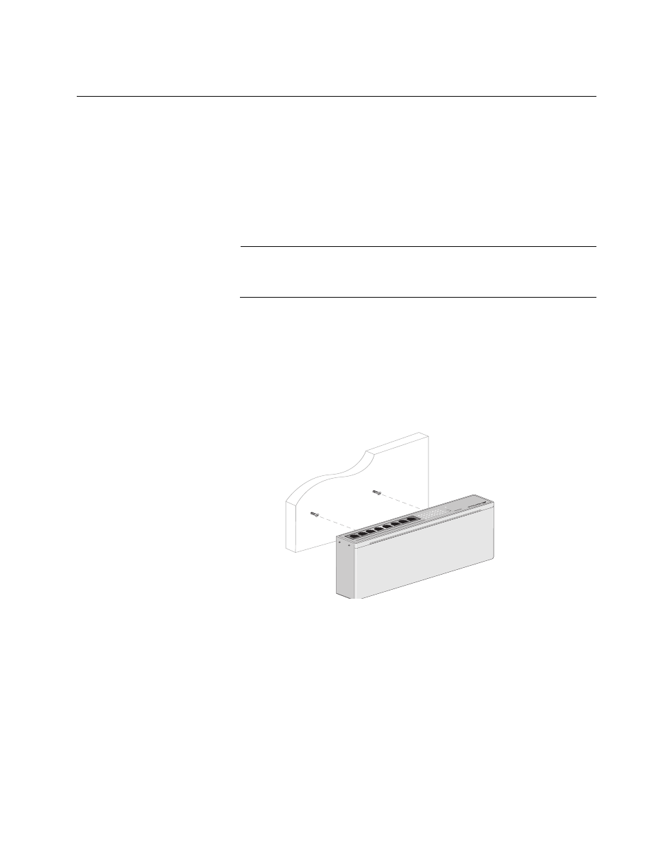
5. Align the keyholes on the back with the screw heads, as shown in
Figure 12. Aligning an AT-GS900/8E Switch for Mounting on the Wall
A T-
GS908L
10
/1
00
/1
00
0B
ase
- T
G
ig
ab
it E
th
ern
et
Sw
itc
h
LIN
K/A
CT
FD
X
PO
WER
10M
100
M
100
0M
1
2
3
4
5
6
7
8
2
3
4
1
6
7
8
5