Chapter 2: installation 36 – Allied Telesis AT-CV1203 User Manual
Page 36
Chapter 2: Installation
36
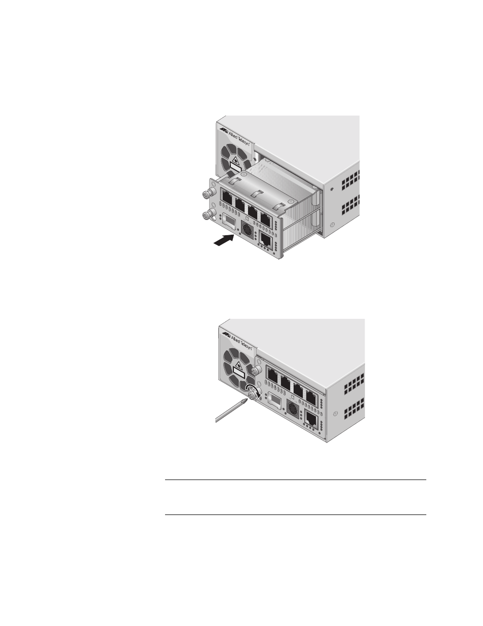
5. Align the back edge of the line card with the bottom left and right
alignment guides located inside the slot.
6. Slide the AT-CM70S line card into the chassis, as shown in Figure 16,
until the slot cover is flush with the front of the chassis.
Figure 16. Inserting an AT-CM70S Line Card
7. Use a Phillips screwdriver to tighten the captive screws on the line
card, as shown in Figure 17.
Figure 17. Tightening the Captive Screws
Note
Always tighten the captive screws to secure the line card to the
chassis.
Refer to the documentation shipped with your line card for cabling
information.
AT-CV1200
AT-CV120
0
CLASS
1
LASER P
RO
DUC
T
903
A
T
-CM70S
LK O
A
M
F
P
CPU RESET
C
O
N
S
O L
E
L/A FD 100
2
AIS
1
23
4
1
23
4
4
3
LO
TC
NML
1
RCL
NML
T
X
RD
Y
T1/E1
TEST
S
AT-CV120
0
CLASS
1
LASER PRODUC
T
904
A
T
-CM70S
LK O
A
M
F
P
CPU RESET
C
O
N
S
O L
E
L/A FD 100
2
AIS
1
23
4
1
23
4
4
3
LO
TC
NML
1
RCL
NML
T
X
RD
Y
T1/E1
TEST
S