Front and back panels, Additional at-cv1203 chassis features – Allied Telesis AT-CV1203 User Manual
Page 17
AT-CV120x Two-Slot Chassis Installation Guide
17
available from your Allied Telesis sales representative.
Front and Back
Panels
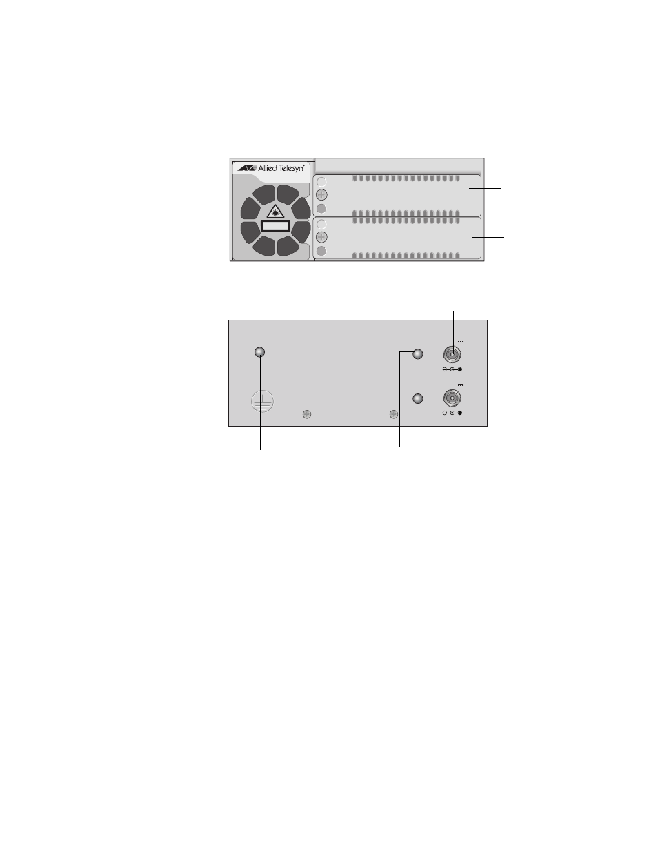
Figure 2 shows the front and back panels of the AT-CV1200 chassis. The
AT-CV1203 chassis is physically identical.
Figure 2. AT-CV120x Chassis Front and Back Panels
Additional
AT-CV1203
Chassis Features
In addition to the standard AT-CV120x chassis features, the AT-CV1203
chassis supports two additional features:
Dying Gasp: If the power to the backplane drops below a
predetermined level, an interrupt is sent to the line cards in the chassis
indicating that the power is about to go down. Any AT-CM series line
card that is compliant with the Dying Gasp feature sends a Dying Gasp
message over the fiber cable to its link partner with information that the
connection is about to fail.
Redundant Power Supply Failure: When an AT-CV1203 chassis has
two power supplies and an AT-CV5M0x Management Card installed, if
one of the two power supplies fails, the management card detects this
failure and sends the information to the local user as well as to the
remote chassis through the line card.
544
AT-CV1200
2
1
CLASS 1
LASER PRODUCT
545
12VDC
12VDC
PWR A
PWR B
PWR GOOD
Slot 1
Slot 2
Power Adapter LEDs
PWR Good LED
AC Power Connector (PWR A)
AC Power Connector (PWR B)