Chapter 2: installation 34, Class 1 laser produc t, Rd y – Allied Telesis AT-CV1203 User Manual
Page 34
Chapter 2: Installation
34
5. Set the line card’s DIP switches if necessary.
For more information on the DIP switch settings, refer to the
documentation shipped with your line card.
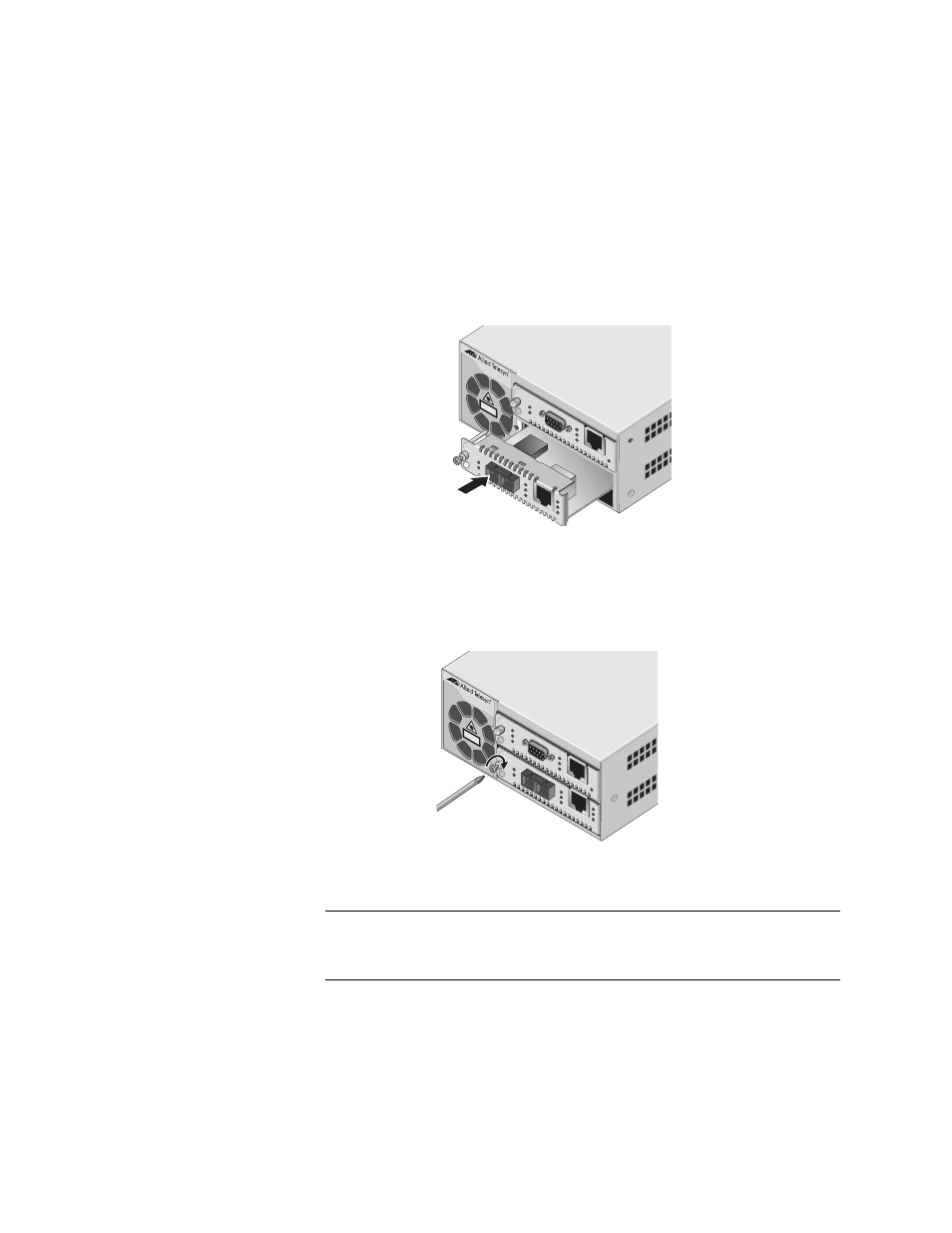
6. Align the back edge of the line card with the left and right alignment
guides located inside the slot.
7. Slide the line card into the slot, as shown in Figure 13, until the slot
cover is flush with the front of the chassis.
Figure 13. Inserting a Line Card
8. Use a Phillips screwdriver to tighten the captive screw on the line card,
Figure 14. Tightening the Captive Screw
Note
Always tighten the captive screw to secure the line card to the
chassis.
Refer to the documentation shipped with your line card for cabling
information.
AT-CV120
0
AT-CV120
0
CLASS
1
LASER PRODUC
T
547
A
T
-CM20
2
LK A
T
S
F
P
LK A
T
FD
S
ML ML O
A
M
T
X
RD
Y
A
T-CV5M0
1
LK A
T
FL
T
LK A
T
FD
CPU RE
S
ET
T
X
1
RD
Y
AT-CV120
0
CLASS
1
LASER PRODUC
T
A
T
-CM20
2
LK A
T
LK A
T
FD
S
ML ML O
A
M
T
X
548
A
T-CV5M0
1
LK A
T
FL
T
LK A
T
FD
CPU RE
S
ET
T
X
1
2