Rps connector port pinouts, Figure 30. rps 16-pin molex connector pin layout – Allied Telesis AT-8550SP User Manual
Page 87
AT-8500 Series Layer 2+ Fast Ethernet Switches Installation Guide
87
RPS Connector Port Pinouts
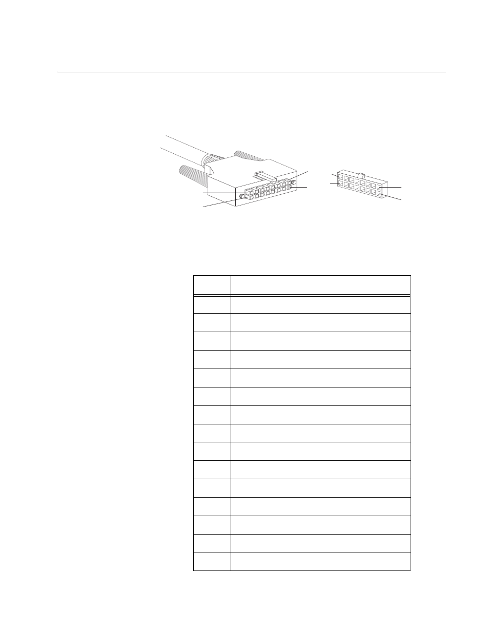
Figure 30 illustrates the pin layout to the 16-pin molex connector and RPS
port on the AT-8516F/SC, AT-8524M, AT-8550GB, and AT-8550SP
switches.
Figure 30. RPS 16-pin Molex Connector Pin Layout
Table 16 lists the 16-pin RPS connector pins and definitions.
16
8
9
1
9
1
16
8
Table 16. Pin Definitions of the 16-pin RPS Connector
Pin
Definition
1
+5V DC
2
Remote Sense (RS) +3.3 V DC
3
RS -3.3 V DC
4
RS +2.5V DC
5
Redundant Power Supply (RPS) present
6
+2.5V DC Return
7
+3.3V DC Return
8
+3.3V DC
9
+5V DC Return
10
+2.5V DC
11
+2.5 DC Return
12
+2.5V DC
13
+2.5V DC Return
14
+2.5V DC
15
+3.3V DC
This manual is related to the following products: