Network topologies, Power workgroup topology, Collapsed backbone topology – Allied Telesis AT-8550SP User Manual
Page 43: Figure 9. power workgroup topology 35, Figure 9. power workgroup topology
AT-8500 Series Layer 2+ Fast Ethernet Switches Installation Guide
43
Network Topologies
This section illustrates several of the network topologies you can create
with the AT-8500 Series Fast Ethernet switch.
Power
Workgroup
Topology
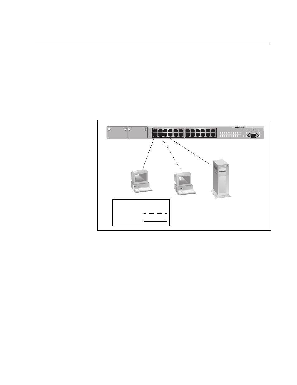
The topology shown in Figure 9 is commonly referred to as a power
workgroup topology. Each workstation or end node is connected directly to
a port on an AT-8524M Fast Ethernet Switch. This provides each end
node with a dedicated data link to the switch for best performance and
reliability. The devices can operate at either 10 Mbps or 100 Mbps.
Figure 9. Power Workgroup Topology
Collapsed
Backbone
Topology
In the topology illustrated in Figure 10, an AT-8524M Fast Ethernet Switch
connects together 10/100 Mbps Ethernet hubs. This type of topology is
often referred to as a collapsed backbone topology. The switch functions
as the focal point of the network by acting as a bridge between the
different workgroups. The switch transfers an Ethernet frame from hub to
hub only when the destination end node for the frame is on a different hub
than the end node that originated the frame. This reduces the amount of
unnecessary data traffic in each workgroup, freeing up bandwidth and
improving network performance.
MODE
STA
TUS
AT-8524M
Fast Ethernet Swit
ch
Legend
10 Mbps
100 Mbps
AT-8524M Fast
Ethernet Switch