Collapsed backbone, Figure 8: collapsed backbone - hub topology – Allied Telesis AT-FS750/24POE User Manual
Page 31
AT-FS750/24POE Fast Ethernet Smart Switch Installation Guide
31
Collapsed
Backbone
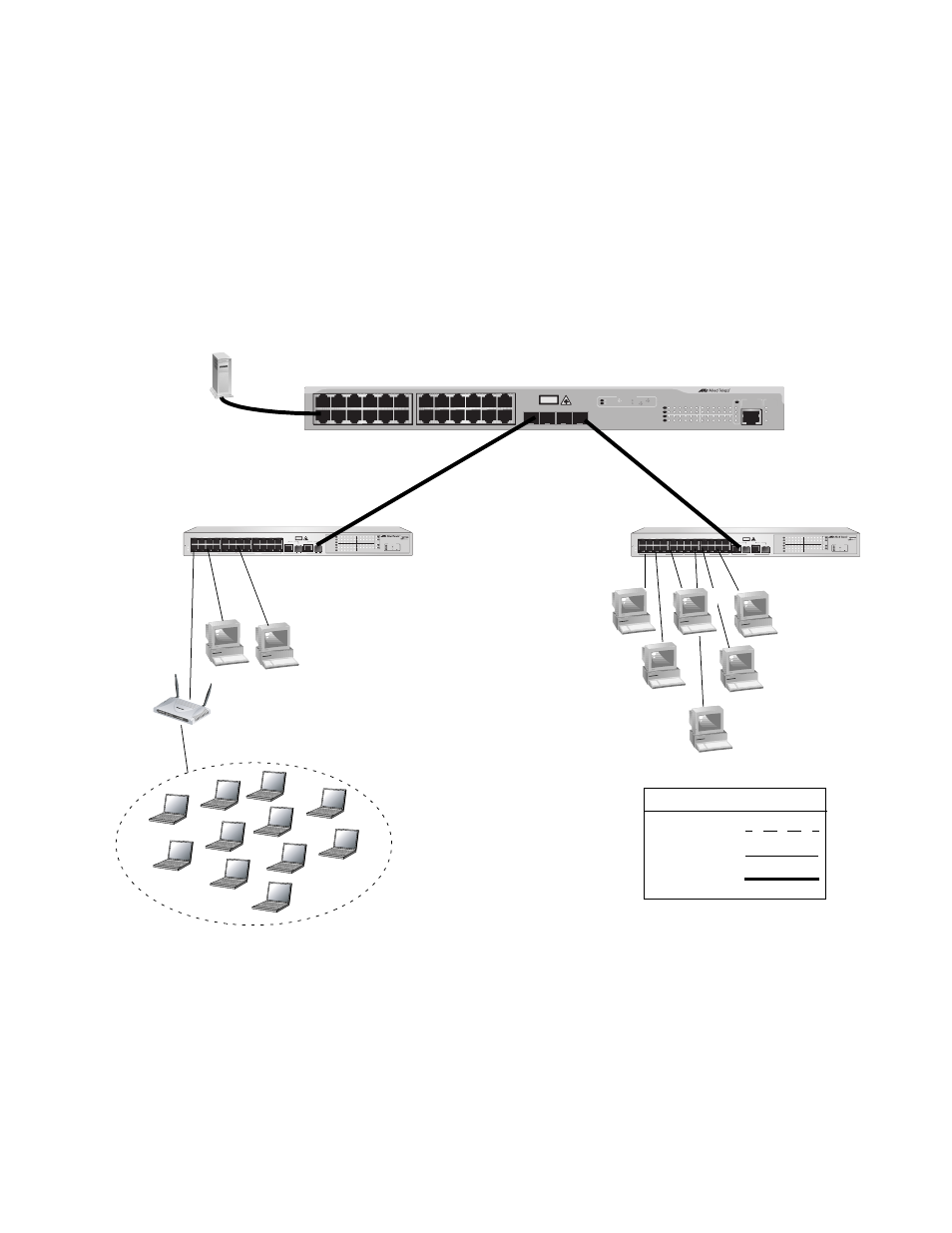
In the topology illustrated in Figure 7, an AT-9424T/SP Gigabit Ethernet
Switch forms the backbone that connects to servers and AT-FS750/
24POE Fast Ethernet Smart switches using Gigabit Ethernet uplinks. This
type of topology is often referred to as a collapsed backbone topology. The
switch functions as the focal point of the network and transfers an Ethernet
frame between the Fast Ethernet switches only when the destination end
node for the frame is on a different switch than the end node that
originated the frame. This reduces the amount of unnecessary data traffic
in each workgroup, freeing up bandwidth and improving network
performance.
Figure 7. Collapsed Backbone - Hub Topology
1
3
5
7
9
11
13
15
17
19
21R
23R
2
4
6
8
10
12
14
16
18
20
22R
24R
CLASS 1
LASER PRODUCT
AT-9424T
1
3
5
7
9
11
13
15
17
19
21R 23R
2
4
6
8
10
12
14
16
18
20
22R 24R
TERMINAL
PORT
FAULT
MASTER
POWER
STATUS
SFP
21
22
23
24
L/A
D/C
D/C
L/A
D/C
L/A
1000 LINK / ACT
HDX / COL
FDX
10/100 LINK / ACT
PORT ACTIVITY
21
22
23
24
SFP
L/A
Gigabit Ethernet Switch
1282
1088
AT-FS750/24POE
24 Port 10/100 Mbps WebSmart Switch
with 2 Combo Uplinks + 12 POE Ports
2
3
4
5
6
7
8
9
10
12
11
13
14
15
16
17
18
19
20
21
22
23
24
25
26
PD ON
PD ERROR
LINK
ACT
100M
10M
1000M
100M
PORT ACTIVITY
10M
1
1
3
5
7
9
11
13
15
17
19
21
23
2
4
6
8
10
12
14
16
18
20
22
24
POE
PWR
SYSTEM
10/100 POE PORTS
25
CLASS 1
LASER PRODUCT
SFP
10/100/1000Base-T
26
SFP
10/100/1000Base-T
UPLINK PORTS
10/100 PORTS
Legend
100 Mbps
1000 Mbps
10 Mbps
AT-9424T
AT-FS750/24POE
AT-FS750/24POE
Wireless Network
301