Front and back panels, Figure 2: at-fs750/24poe front and back panels, Class 1 laser product – Allied Telesis AT-FS750/24POE User Manual
Page 17
AT-FS750/24POE Fast Ethernet Smart Switch Installation Guide
17
Front and Back Panels
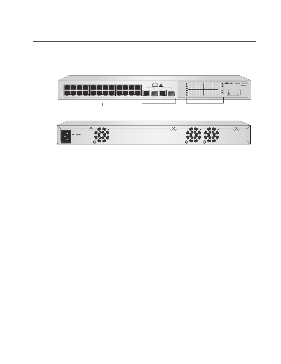
Figure 1 illustrates the front and back panels of the AT-FS750/24POE Fast
Ethernet Smart switch.
Figure 1. AT-FS750/24POE Front and Back Panels
1088
AT-FS750/24POE
24 Port 10/100 Mbps WebSmart Switch
with 2 Combo Uplinks + 12 POE Ports
2
3
4
5
6
7
8
9
10
12
11
13
14
15
16
17
18
19
20
21
22
23
24
25
26
PD ON
PD ERROR
LINK
ACT
100M
10M
1000M
100M
PORT ACTIVITY
10M
1
1
3
5
7
9
11
13
15
17
19
21
23
2
4
6
8
10
12
14
16
18
20
22
24
POE
PWR
SYSTEM
10/100 POE PORTS
25
CLASS 1
LASER PRODUCT
SFP
10/100/1000Base-T
26
SFP
10/100/1000Base-T
UPLINK PORTS
10/100 PORTS
10/100Base Twisted Pair Ports
Port LEDs
Uplink Combo Ports
System LEDs
1089
See also other documents in the category Allied Telesis Computer hardware:
- AT-GS908M (54 pages)
- AT-x230-10GP (80 pages)
- AT-GS950/48PS (64 pages)
- AT-GS950/10PS (386 pages)
- AT-GS950/16PS (386 pages)
- AT-GS950/48PS (386 pages)
- AT-9000 Series (258 pages)
- AT-9000 Series (1480 pages)
- IE200 Series (70 pages)
- AT-GS950/48 (378 pages)
- AT-GS950/48 (60 pages)
- AT-GS950/48 (410 pages)
- AT-GS950/8 (52 pages)
- SwitchBlade x8106 (322 pages)
- SwitchBlade x8112 (322 pages)
- SwitchBlade x8106 (240 pages)
- SwitchBlade x8112 (240 pages)
- AT-TQ Series (172 pages)
- AlliedWare Plus Operating System Version 5.4.4C (x310-26FT,x310-26FP,x310-50FT,x310-50FP) (2220 pages)
- FS970M Series (106 pages)
- 8100S Series (140 pages)
- 8100L Series (116 pages)
- x310 Series (116 pages)
- x310 Series (120 pages)
- AT-GS950/16 (44 pages)
- AT-GS950/24 (404 pages)
- AT-GS950/24 (366 pages)
- AT-GS950/16 (404 pages)
- AT-GS950/16 (364 pages)
- AT-GS950/8 (404 pages)
- AT-GS950/8 (364 pages)
- AT-GS950/8 (52 pages)
- AT-8100 Series (330 pages)
- AT-8100 Series (1962 pages)
- AT-FS970M Series (330 pages)
- AT-FS970M Series (1938 pages)
- SwitchBlade x3106 (288 pages)
- SwitchBlade x3112 (294 pages)
- SwitchBlade x3106 (260 pages)
- SwitchBlade x3112 (222 pages)
- AT-S95 CLI (AT-8000GS Series) (397 pages)
- AT-S94 CLI (AT-8000S Series) (402 pages)
- AT-IMC1000T/SFP (23 pages)
- AT-IMC1000TP/SFP (24 pages)
- AT-SBx3106WMB (44 pages)