Allied Telesis AT-MC1008/SP User Manual
Page 45
AT-MC1008 Series Installation Guide
45
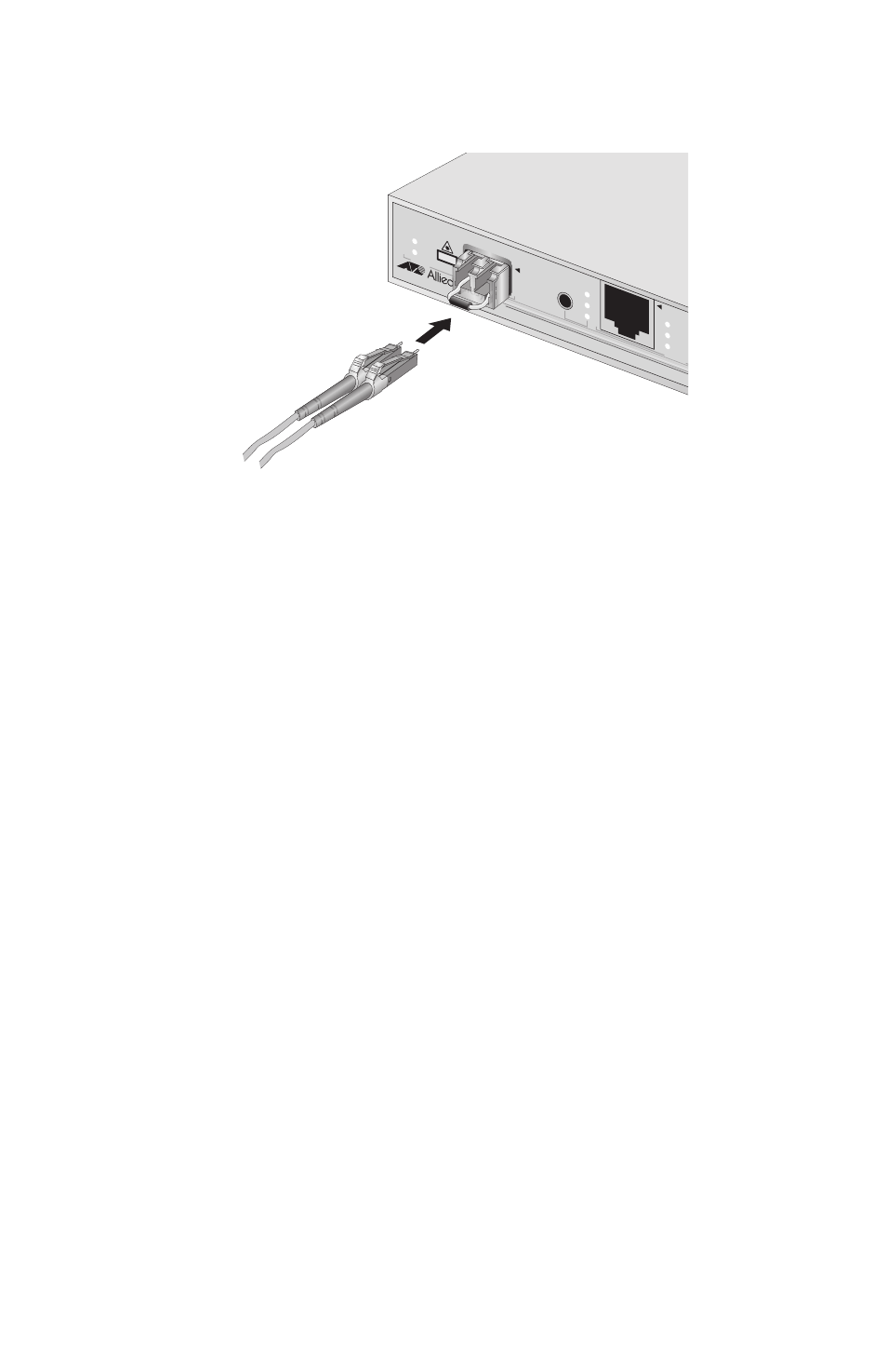
2. Connect the appropriate optical cable to the transceiver, as shown in
Figure 20. Connecting to the SFP Transceiver
When attaching a optical cable, be sure to observe the following
guidelines:
Be sure that the cable connector is firmly locked into place in the
port.
You should verify that you are using the appropriate type of
optical cabling.
You should verify that the operating specifications of the remote
fiber optic port are compatible with the SFP transceiver. For
example, you cannot connect a fiber optic SFP transceiver with a
maximum distance of 40 kilometers and an operating wavelength
of 1550 nanometers (nm) to a remote fiber optic port with an
maximum distance of only 10 kilometers and an operating
wavelength of 1310 nm.
The SFP transceiver consists of two connectors in one slot, as
shown in Figure 20. Each connector connects to a separate fiber
strand. One is for receiving data and the other is for transmitting
data. When connecting a fiber optic cable to a GBIC transceiver,
be sure that the receiver fiber connector is connected to the
transmitter connector on the remote end-node, and the
transmitter fiber connector is connected to the receiver connector
on the remote node.
3. Then connect the other end of the optical cable to the link partner.
AT-MC1008/
SP
GIGABIT ET
HERNET
MEDIA CONVE
RTER
1000Base-
T
PW
R
LIN
K
ACT
ML
SML
LT
MODE
LIN
K
ACT
SFP
CLAS
S 1
LASE
R PR
ODUC
T
POR
T 1
PORT
2
1000Base
AU
TO MDI/M
D
371