Rj-45 connector and port pin layout, Fiber optic port specifications, Rj-45 twisted- pair port pinouts – Allied Telesis AT-MC102XLPCI User Manual
Page 39
AT-MC102XLPCI 100Mbps Media Converter Installation Guide
39
RJ-45 Twisted-
Pair Port Pinouts
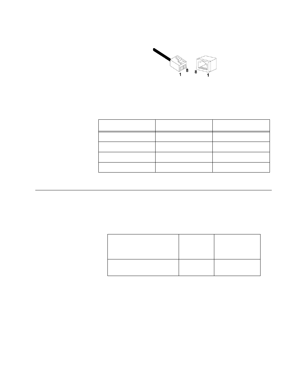
Figure 13 illustrates the pin layout to an RJ-45 connector and port.
Figure 13. RJ-45 Connector and Port Pin Layout
Table 6 lists the MDI and MDI-X RJ-45 pin signals with a twisted-pair port.
Fiber Optic Port Specifications
The cable requirements of the fiber
port are given in Table 7.
The fiber optic specifications are given in the following tables:
❒
Table 8, “Fiber Optic Launch Power” on page 40.
❒
Table 9, “Fiber Optic Receive Power” on page 40.
❒
Table 10, “Fiber Optic Cable Distance” on page 40.
❒
Table 11, “Fiber Optic Loss Specifications” on page 41.
Table 6. RJ-45 Pin Signals for MDI and MDI-X
Pin
MDI Signal
MDI-X Signal
1
TX+
RX+
2
TX-
RX-
3
RX+
TX+
6
RX-
TX-
Table 7. Fiber Optic Cable Loss Budget
Type of Fiber Optic Cable
Maximum
Operating
Distance
Maximum
Allowable Loss
Budget
50/125 or 62.5/125 micron
multimode
2 km (1.2
mi)
13 dB at 1310
nm
- AT-GS908M (54 pages)
- AT-x230-10GP (80 pages)
- AT-GS950/10PS (386 pages)
- AT-GS950/48PS (64 pages)
- AT-GS950/16PS (386 pages)
- AT-GS950/48PS (386 pages)
- AT-9000 Series (1480 pages)
- AT-9000 Series (258 pages)
- IE200 Series (70 pages)
- AT-GS950/48 (410 pages)
- AT-GS950/8 (52 pages)
- AT-GS950/48 (378 pages)
- AT-GS950/48 (60 pages)
- SwitchBlade x8106 (322 pages)
- SwitchBlade x8112 (322 pages)
- SwitchBlade x8106 (240 pages)
- SwitchBlade x8112 (240 pages)
- AT-TQ Series (172 pages)
- AlliedWare Plus Operating System Version 5.4.4C (x310-26FT,x310-26FP,x310-50FT,x310-50FP) (2220 pages)
- FS970M Series (106 pages)
- 8100L Series (116 pages)
- 8100S Series (140 pages)
- x310 Series (120 pages)
- x310 Series (116 pages)
- AT-GS950/24 (404 pages)
- AT-GS950/24 (366 pages)
- AT-GS950/16 (44 pages)
- AT-GS950/16 (364 pages)
- AT-GS950/16 (404 pages)
- AT-GS950/8 (404 pages)
- AT-GS950/8 (364 pages)
- AT-GS950/8 (52 pages)
- AT-8100 Series (330 pages)
- AT-8100 Series (1962 pages)
- AT-FS970M Series (330 pages)
- AT-FS970M Series (1938 pages)
- SwitchBlade x3106 (288 pages)
- SwitchBlade x3112 (294 pages)
- SwitchBlade x3106 (260 pages)
- SwitchBlade x3112 (222 pages)
- AT-S95 CLI (AT-8000GS Series) (397 pages)
- AT-S94 CLI (AT-8000S Series) (402 pages)
- AT-IMC1000T/SFP (23 pages)
- AT-IMC1000TP/SFP (24 pages)
- AT-SBx3106WMB (44 pages)