2 thermal solution design requirements, 3 sample heat sinks and attachment methods, Thermal solution design requirements – AMD 1207 User Manual
Page 30: Sample heat sinks and attachment methods, Table 7
30
Thermal Design of Custom 2U-4P Systems
Chapter 5
32800
Rev. 3.00
August 2006
Thermal Design Guide for Socket F (1207) Processors
Depending on the system features and layout, more space around the socket may be available for the
thermal solution than is shown in Figure 8 on page 29. This space permits heat sink designs with
better thermal performance.
Appendix C on page 53 shows a complete, detailed set of keep-out drawings for custom 2U-4P
systems based on socket F (1207) processors.
5.2
Thermal Solution Design Requirements
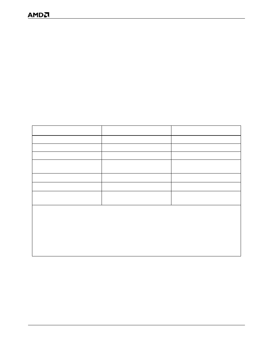
Table 7 provides the design-target specifications that must be met for socket F (1207) processors to
operate reliably in a typical 2U-4P system based on socket F (1207) processors.
5.3
Sample Heat Sinks and Attachment Methods
The following sections provide one possible thermal design solution and the specifics on attaching
that solution to the motherboard.
Table 8 on page 31 lists the parts used in the thermal reference design for Custom 2U-4P systems
based on socket F (1207) processors.
Table 7.
Thermal Solution Design Requirements for Custom 2U-4P Systems
Symbol
Description
Maximum
L
Length of heat sink
92 mm
W
Width of heat sink
58 mm
H
Height of heat sink
40 mm
θ
ca
Case-to-ambient thermal
resistance
0.26°C/W
1, 2, 3
M
HS
Mass of heat sink
450 g to 700 g
F
clip
Clip force
75 lbs ±15 lbs
T
A
Local ambient temperature near
processor
38°C
Notes:
1. This is the thermal resistance required for dual-core, 90-nm socket F (1207) processors. The thermal resistance
requirement may vary depending on the product OPN. The user should consult the processor data sheet for the
thermal requirements specific to the part.
2. Heat sinks weighing up to 450 g can be attached to the motherboard. Heat sinks weighing over 450 g should be tied
directly to the chassis for more reliable shock and vibration performance.
3. This chapter describes a heat sink weighing less than or equal to 450 g. Design examples of solutions up to 700 g are
in development.