2 thermal solution design requirements, 3 sample heat sinks and attachment methods, Thermal solution design requirements – AMD 1207 User Manual
Page 22: Sample heat sinks and attachment methods, Table 4
22
Thermal Design of Custom 1U-2P Systems
Chapter 4
32800
Rev. 3.02
August 2006
Thermal Design Guide for Socket F (1207) Processors
Depending on the system features and layout, more space around the socket may be available for the
thermal solution than is shown in Figure 4 on page 21. This space permits heat sink designs with
better thermal performance.
Appendix B on page 45 shows a complete, detailed set of keep-out drawings for custom 1U-2P
systems based on socket F (1207) processors.
4.2
Thermal Solution Design Requirements
To maintain the case temperature of the processor below the maximum specification, certain heat sink
design parameters must be considered. Table 4 provides the design-target specifications that must be
met for socket F (1207) processors to operate reliably.
4.3
Sample Heat Sinks and Attachment Methods
The following sections provide one possible thermal design solution and the specifics on attaching
that solution to the motherboard.
Table 5 on page 23 lists the parts used in the thermal reference design solution for 1U-2P systems
based on socket F (1207) processors.
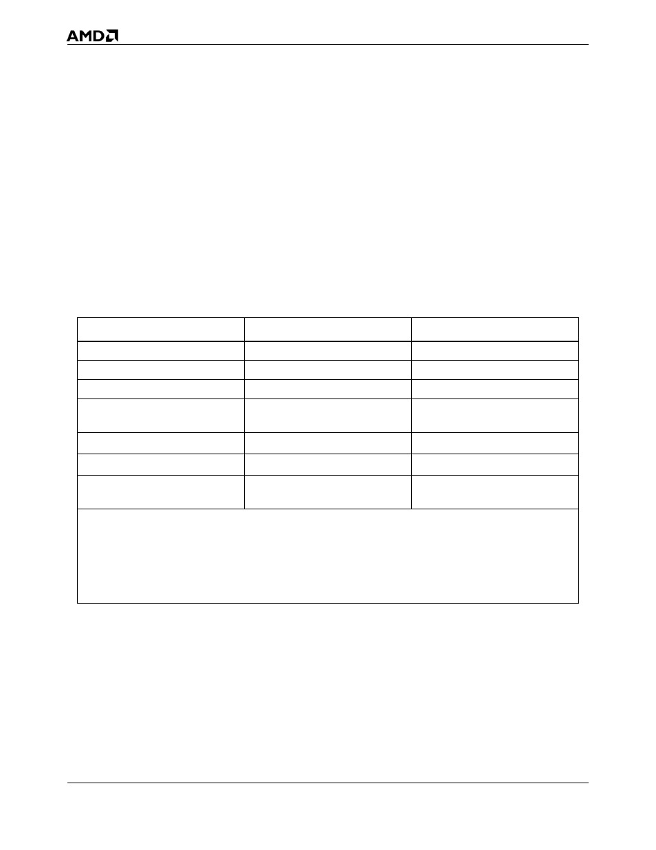
Table 4.
Thermal Solution Design Requirements for Custom 1U-2P Systems
Symbol
Description
Maximum
L
Length of heat sink
87 mm
W
Width of heat sink
74 mm
H
Height of heat sink
28 mm
θ
ca
Case-to-ambient thermal
resistance
0.26°C/W
1, 2, 3
M
HS
Mass of heat sink
450 g to 700 g
F
clip
Clip force
75 lbs ±15 lbs
T
A
Local air temperature entering
processor heat sink
38°C
Notes:
1. This is the thermal resistance required for dual core, 90-nm socket F (1207) processors. The thermal resistance
requirement may vary depending on the product OPN. The user should consult the processor data sheet for the
thermal requirements specific to the part.
2. Heat sinks weighing up to 450 g can be attached to the motherboard. Heat sinks weighing over 450 g should be tied
directly to the chassis for more reliable shock and vibration performance.
3. This chapter describes a heat sink weighing less than or equal to 450 g.