Connecting the mains voltage, Isolating transformer, 4 "isolating transformer") – A.O. Smith 120 through 250 Series User Manual
Page 34
Installation
34
Instruction manual BFC
3
is
In preparation, you must first remove the two plastic covers and the protective
cap of the electrical section.
1. Undo the screws of the plastic covers.
2. Carefully remove the covers from the appliance.
The electrical section is now visible.
3. Loosen the 2 screws (A) of the electrical section, and remove the protective
cap (B) from the electrical section.
The connector block (C) is now visible.
Note
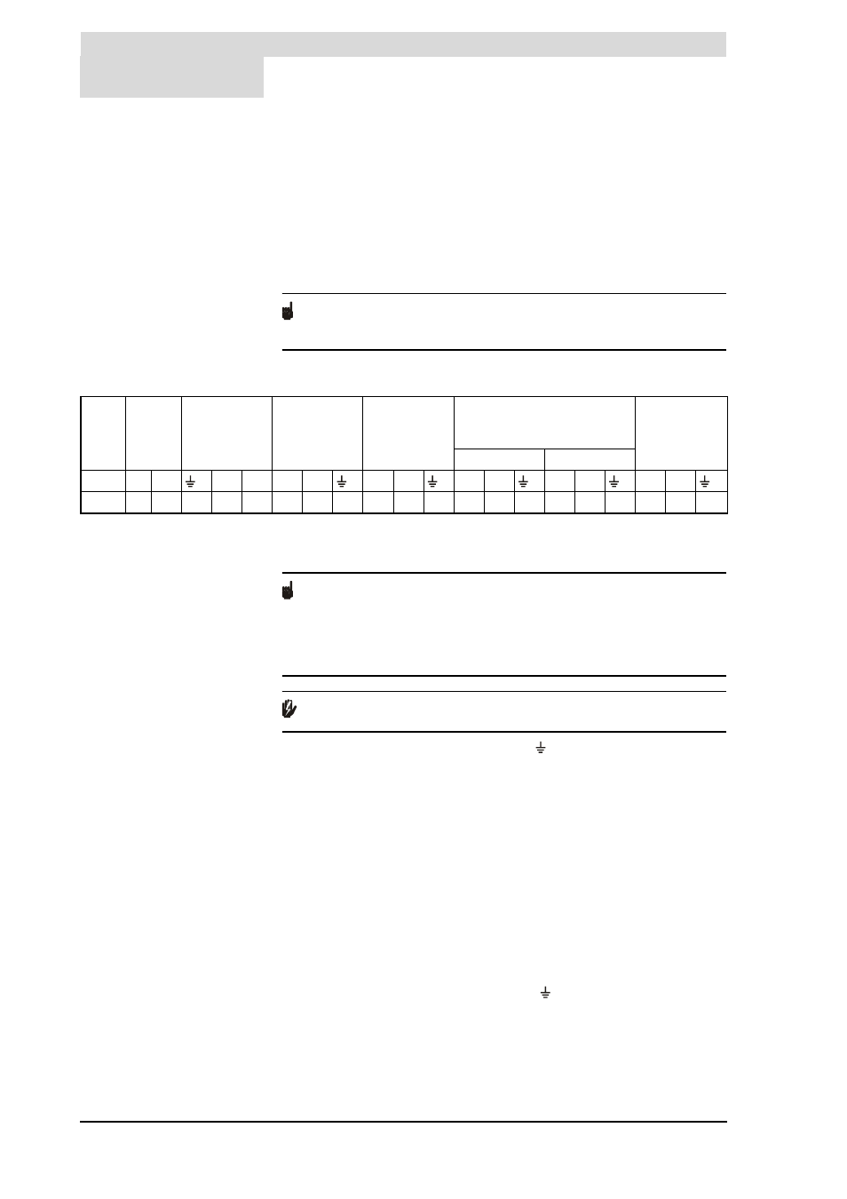
Consult the table for the connections and consult the electrical diagram for
the electrical component connections.
Electrical connector block
3.10.3
Connecting the mains voltage
The appliance is supplied without a power cable and isolator.
Note
In order to receive electrical power, the appliance has to be connected to the
mains power by means of a permanent electrical connection. A double-pole
isolator with a contact gap of at least 3 mm must be fitted between this
permanent connection and the appliance. The power cable must have cores of
at least 3 x 1.0 mm
2
.
Warning
Leave the appliance isolated until you are ready to start it up.
1. Connect phase (L), neutral (N) and earth ( ) of the power cable to terminals
22 through 24 of the connection block as indicated in the
table
2. Fit the power cable in the strain relief.
3. Connect the power cable to the isolator.
4. If you have no more connections to make:
-
Fit the cap on the electrical terminal block.
-
Fit the plastic covers onto the appliance.
3.10.4
Isolating transformer
An isolating transformer should be used if there is a case of 'floating neutral'.
1. Refer to fitting instructions provided with the isolating transformer. (Contact
the supplier for details of the correct isolating transformer.)
2. Connect phase (L), neutral (N) and earth ( ) to terminals 16 through 21 of
the terminal block as stated in the table
3. Fit the cables in the strain relief.
Unus
ed
Tank
ON
Continuous
pump
Program-
controlled
pump
Alarm Off
Isolating transformer
Mains
voltage
primary
secondary
X1 X2
L
N
N
L
X1
X2
N
L
N
L
N
L
1-4
5
6
7
8
9
10
11
12
13
14
15
16
17
18
19
20
21
22
23
24