Parallel connections – A.O. Smith 120 through 250 Series User Manual
Page 31
Instruction manual BFC
31
is
3.9.4
Parallel connections
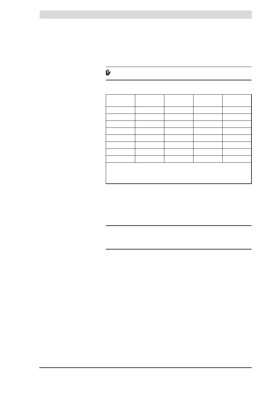
The table states the maximum pipe lengths for parallel systems. The maximum
pipe length depends on the chosen diameter.
Warning
Install flue component pipe runs with a run-off of 5 mm per metre.
Flue gas outlet requirements for parallel systems
You must use the longest pipe when calculating the pipe length. For example, if
the chimney pipe is 35 metres and the air supply pipe is 32 metres, use 35
metres as the length for the calculation. Next, add the L
equivalent
for every 90°
and 45° bend to this 35 metres, in both the air supply and flue gas outlet. The
following practical example illustrates how to use the table.
Practical example of parallel flue gas outlet
Example
The diagram shows a BFC 30. This has to be fitted with a 25m parallel pipe
100mm in diameter, plus eight 90-degree bends. The configuration must be
checked for compliance with the requirements stated in the table.
Appliance
Diameter
1
Maximum
total length
L
equivalent
90º bend
L
equivalent
45º bend
BFC 28
80mm
25m
3.9m
1.1m
BFC 30
100mm
80m
4.6m
1.2m
BFC 50
100mm
45m
4.6m
1.2m
BFC 60
100mm
25m
4.6m
1.2m
BFC 28
100mm
100m
4.6m
1.2m
BFC 30
130mm
100m
2.4m
1.4m
BFC 50
130mm
100m
2.4m
1.4m
BFC 60
130mm
100m
2.4m
1.4m
1) Parallel systems with diameter of 130mm or 150mm. If the maximum total
length for a diameter of 130mm is insufficient, 150mm diameter must be used.
Any diameter enlargement must be carried out on both air supply and flue gas
outlet.