Installation diagram, Instruction manual bfc 23, 5 installation diagram – A.O. Smith 120 through 250 Series User Manual
Page 23
Instruction manual BFC
23
is
3.5
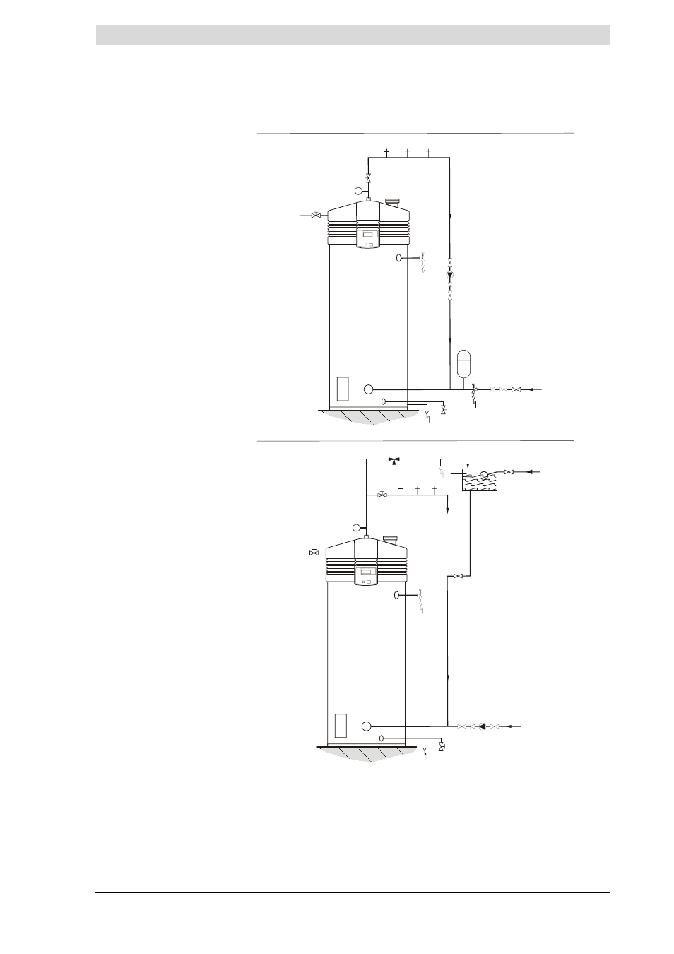
Installation diagram
Installation diagram
Legend
Only applicable numbers are
mentioned.
1. pressure reducing valve
(mandatory)
3. T&P valve (mandatory)
4. stop valve (recommended in
pipe C and mandatory in pipe A)
5. non-return valve (mandatory)
6. circulation pump (optional)
9. drain valve
10. manual gas valve (mandatory)
11. service stop valve
12. temperature gauge (optional)
13. condensation drainage
14. hot water draw-off points
15. expansion valve (mandatory)
16. expansion vessel (mandatory)
17. 3-way aeration valve
(recommended)
18. water tank
19. float valve
A. cold water supply
B. hot water supply
C. circulation pipe
D. gas supply
E. overflow pipe
H. overflow pipe
IMD-0464 R0
T
B
A
4
17
E
H
C
C
10
3
D
13
9
4
6
4 5
14
11
4
18
12
19
A
4
5
C
1
15
16
13
9
4
5
6
4
14
14
14
11
10
D
B
3
T
12
UNVENTED
VENTED
- ACGSS02407 (4 pages)
- 401 (48 pages)
- 6-119 (28 pages)
- 1850 (36 pages)
- ADMP - 60 (6 pages)
- 750 (24 pages)
- 505 (2 pages)
- BTX-100 (2 pages)
- GW/GWO-2500 (4 pages)
- NW 37-670 (12 pages)
- BTP(V)-740A (6 pages)
- Genesis GB-1500 (2 pages)
- VWT-1000 (4 pages)
- AOSTT35300 (4 pages)
- 1300 (12 pages)
- BTP-199 (4 pages)
- ADM - 135 (74 pages)
- 1000 (80 pages)
- BTH-500A (8 pages)
- BTH 300A (36 pages)
- BTH 400A (36 pages)
- DB-720 thru 1810 (4 pages)
- BTP-378A (2 pages)
- BTI 120 (32 pages)
- AOSRG45300 (2 pages)
- AOSRG46600 (2 pages)
- VB/VW- 750 (52 pages)
- 300A (40 pages)
- 185363-001 (32 pages)
- AOSRE50400 (2 pages)
- TC-099 (74 pages)
- 25 litres (11 pages)
- ATI-705N (2 pages)
- XGV-50 200/201 (2 pages)
- 12 50GPC T 100 (56 pages)
- GB/GW-200 (10 pages)
- GWT-2500 (4 pages)
- VB 750 (8 pages)
- BTH 400 (1 page)
- 000 (4 pages)
- LB/LW: 500 (12 pages)
- VW-500 through VW-1000 (4 pages)
- BT-100 (2 pages)
- BTI-80 (2 pages)
- Voltex Hybrid Electric PHPT-80 (20 pages)