Draft hood/damper installation flue outlet reducer – American Water Heater DCG User Manual
Page 9
9
9
Draft Hood/Damper Installation
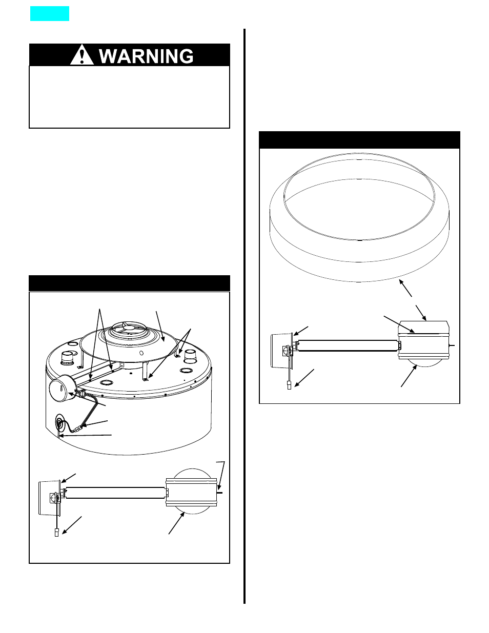
Flue Outlet Reducer
Some units are shipped with a flue outlet reducer (See
Figure 3B). Use only the flue outlet reducer supplied
with this unit. The flue outlet reducer should be
connected to the top of the flue damper and sealed by
high temperature silicon.
The vent pipe must be installed according to all local
and state codes or, in the absence of local and state
codes, the “National Fuel Gas Code”, ANSI
Z223.1(NFPA 54)-latest edition.
Figure 3B: Flue Outlet Reducer
Damper in OPEN position
Damper wiring harness
Damper motor
Flue outlet reducer
High
temperature
silicon sealant
Install the supplied draft hood and damper on the flue
outlet collar. Use only the supplied draft hood and
damper, DO NOT use any substitute or alter the
components in any way.
Place the damper on the water heater (see figure 3A).
Align the four pilot holes on top of the water heater with
the 4 corresponding holes on the damper bracket and
secure with the supplied screws. Next, align the draft
hood legs with the 4 corresponding pilot holes on top of
the water heater and attach securely with the supplied
screws. Locate the wiring from the ECO, and attach it to
the wiring harness on the damper (see Figure 3A).
Once damper is installed, ensure that the damper posi-
tion indicator is visible (See figure 3A).
Do not operate water heater with damper
in closed position, it must be in the open
position during water heater operation.
Do not negate the action of any existing
safety or operational controls.
Bracket screws
Draft hood screws
Draft hood
Damper motor
Damper wiring harness
ECO wiring harness
Damper in OPEN position
Damper wiring harness
Damper motor
Damper position indicator
Figure 3A: Flue Damper Assembly
Index