Tracer system status, Figure 2, Tracer 5045 system status – ADTRAN TRACER 5045 User Manual
Page 42: Tracer s
Section 5 User Interface Guide
TRACER 5045 System Manual
42
© 2004 ADTRAN, Inc.
612805045L1-1B
>TRACER S
YSTEM
S
TATUS
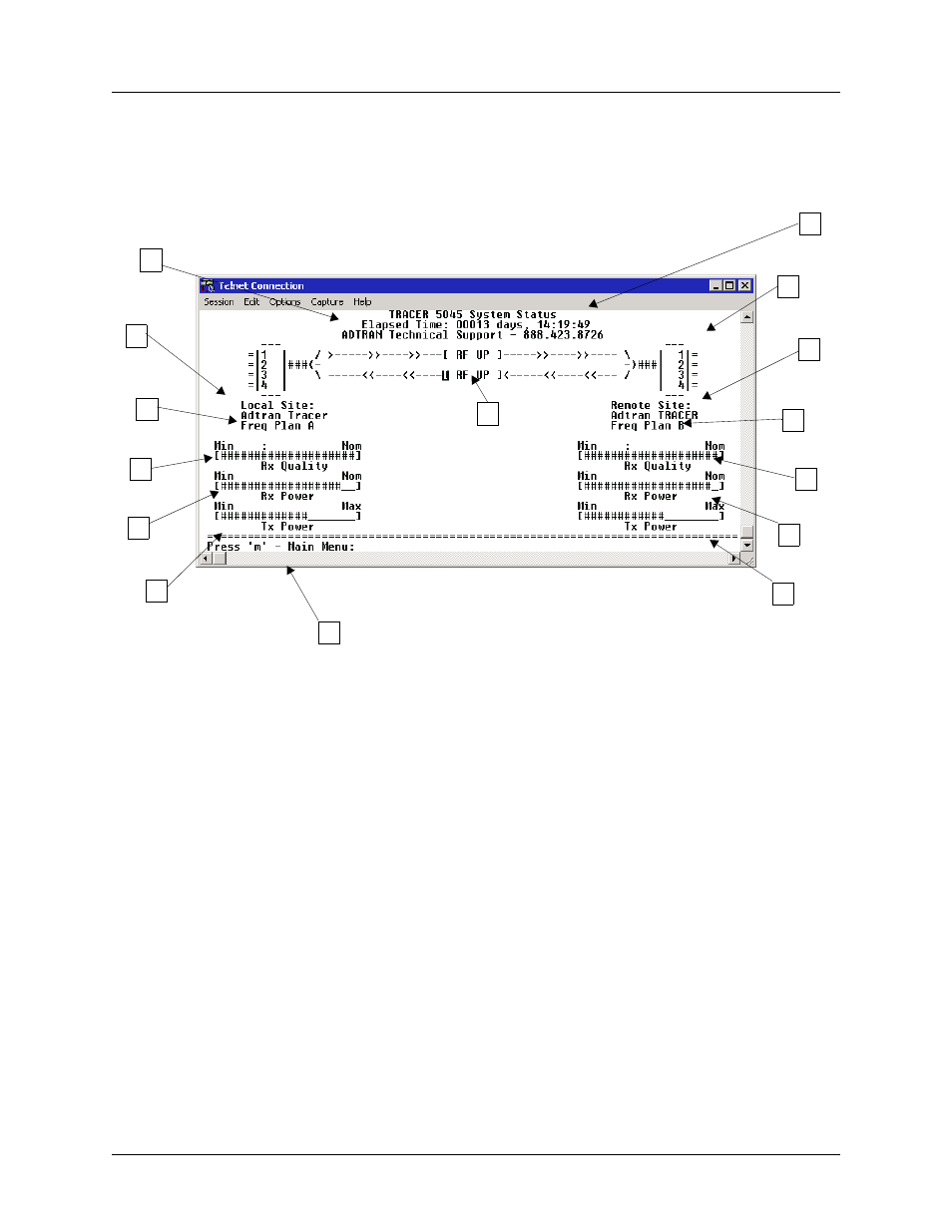
Figure 2 shows the TRACER 5045 System Status menu page. The status of major system components for
both sides of the TRACER link are displayed, but no configuration can be performed from this view.
Figure 2. TRACER 5045 System Status
A. Elapsed Time
The top of the TRACER 5045 System Status menu page displays the elapsed time the TRACER 5045
system has been operational since the last power reset.
B. Contact Information
The ADTRAN technical Support toll-free contact number is located directly beneath the elapsed time
display at the top of the TRACER 5045 System Status menu page.
C. RF Status
A graphical indicator of the TRACER RF links is located beneath the Technical Support contact
number. The status of the received radio link is indicated as
RF U
P
or
RF D
OWN
for each direction.
This RF status display corresponds to the
RF DOWN
LED on the front of the unit.
D. Ethernet Status
A visual status of the current configuration for each 10/100BaseT/TX Ethernet interface (for both the
local and remote TRACER systems) is provided on the TRACER 5045 System Status menu page. The
current operational speed of each Ethernet interface (
10BT
or
100BT
) indicates whether the interface is
10BaseT or 100BaseTX. A blank line next to the port number indicates there is no active Ethernet link
A
Elapsed
Time
B
Contact
Information
F
Local
G
Frequency
I
Rx Power
C
RF Status
D
Ethernet
E
Remote
G
I
Rx Power
J
Tx Power
J
Tx Power
K
Navigation Reminder
Status
Tracer
STATUS
Plan
Frequency
Plan
TRACER
Status
H
Rx Quality
H
Rx Quality