Receiver sensitivity, Antenna information, Antenna alignment – ADTRAN TRACER 5045 User Manual
Page 19: Table 3, Path loss for given path lengths
TRACER 5045 System Manual
Section 2 Microwave Path Engineering Basics
612805045L1-1B
© 2004 ADTRAN, Inc.
19
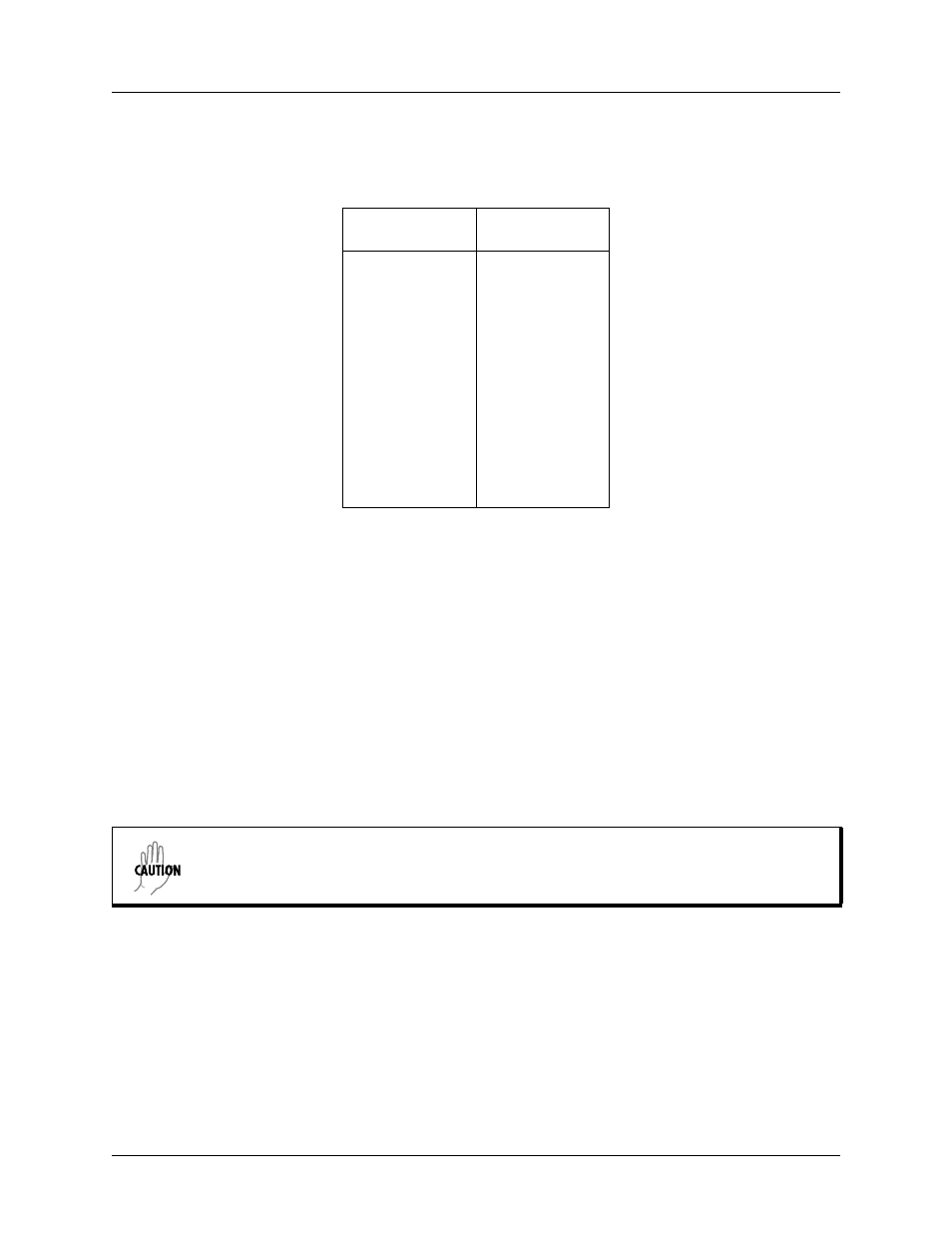
Table 3 lists path loss values for various path lengths for the TRACER 5045 5.8 GHz system. Values not
listed in the table can be interpolated from those listed.
5.
RECEIVER SENSITIVITY
Receiver sensitivity is a value expressed in decibels referenced to one milliwatt (dBm) that corresponds to
the minimum amount of signal power needed at the receiver to achieve a given bit error rate (BER).
Receiver sensitivity is usually a negative number of decibels, and smaller receiver sensitivity (higher
quantity negative number) is better for a given BER. Several factors affect receiver sensitivity, including
the data bandwidth of the wireless link and the amount of additional signal degradation introduced in the
receiver electronics. The receiver sensitivity of the TRACER 5045 is -78 dBm at 10
-6
BER.
6.
ANTENNA INFORMATION
The overall wireless system is directly affected by the antenna selection and installation, discussed in the
following sections.
Antenna Alignment
With line-of-sight microwave communications, optimum system performance requires that the
transmitting and receiving antennas are properly aligned. This ensures maximum received signal power at
each receiver. Antenna alignment must be achieved in both azimuth (along a horizontal plane) and
elevation (along a vertical plane). By ensuring maximum received signal strength, a received signal
strength indicator (RSSI) helps the equipment installer to determine when alignment is maximized.
Table 3. Path Loss for Given Path Lengths
Path Length
(miles)
Path Loss
(dB)
1
112
2
118
3
121
4
124
5
126
10
132
15
135
20
138
25
140
30
141
35
143
Verify the antenna installation meets all regulations specified in the National Electric
Code (NEC) Article 810.