Equipment dimensions, Power requirements, Reviewing the front panel design – ADTRAN TRACER 5045 User Manual
Page 24: Rssi monitoring interface, Front panel leds, Rssi monitoring interface front panel leds, Figure 1, Tracer 5045 front panel layout, Table 1, Tracer 5045 front panel description
Section 3 Engineering Guidelines
TRACER 5045 System Manual
24
© 2004 ADTRAN, Inc.
612805045L1-1B
1.
EQUIPMENT DIMENSIONS
The TRACER 5045 unit is 17.22” W, 9.34” D, and 1.72” H, weighs 7 lbs, and can be used in rackmount
configurations.
2.
POWER REQUIREMENTS
The TRACER 5045 system has a maximum power consumption of 23 W and a maximum current draw of
1.1 A (at 21 VDC).
3.
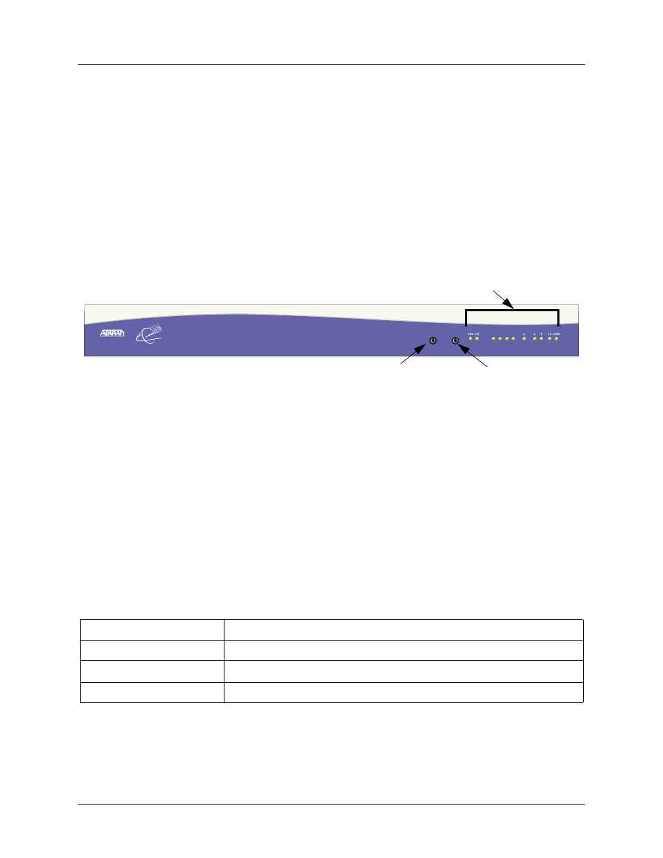
REVIEWING THE FRONT PANEL DESIGN
The front panel contains an
RSSI
monitoring interface, a
GND
interface for reference with RSSI, and status
LEDs to provide visual information about the TRACER 5045 system. Figure 1 identifies the various
bantam interfaces and the LEDs.
Figure 1. TRACER 5045 Front Panel Layout
RSSI Monitoring Interface
The RSSI voltage is a function of the signal strength at the receiver and is used to measure the received
signal strength. RSSI varies from approximately 0 to 5 VDC. An RSSI calibration sheet is shipped with the
system to provide the installer a cross-reference between actual received signal level (in dBm) and RSSI
voltage. This sheet is useful for verifying link budget calculations and ensuring proper equipment
installation.
Front Panel LEDs
With the TRACER 5045 powered-on, the front panel LEDs provide visual information about the status of
the TRACER 5045 system. Table 1 provides a brief description of the front panel features, and Table 2 on
page 25 provides detailed information about the LEDs.
Table 1. TRACER 5045 Front Panel Description
Feature
Description
RSSI Interface
DC voltage indicating strength of the received signal at the antenna
GND Interface
Ground reference for the
RSSI
interface
Status LEDs
Status information about the system
LAN
WAN
PLAN
RF
1
GND
RSSI
2
3
4
TRACER 5045
Status LEDs
GND
RSSI