Quarter bridge strain, 1 quarter bridge strain with 3 wire strain element – Campbell Scientific 4WFBS120, 4WFBS350, 4WFBS1K 4 Wire Full Bridge Terminal Input Modules User Manual
Page 10
4WFBS120, 4WFBS350, 4WFBS1K 4 Wire Full Bridge Terminal Input Modules (TIM)
function used in CRBasic uses this raw output as its input to calculate µstrain.
See Section 4.5 Calculation of Strain for ¼ Bridge Circuits for a detailed
derivation of the equations used.
4. Quarter Bridge Strain
A "quarter bridge strain circuit" is so named because an active strain gage is
used as one of the four resistive elements that make up a full Wheatstone
bridge. The other three arms of the bridge are composed of inactive elements.
There are various circuits that use a single active element, including 2-Wire
gauges, 3-Wire gauges, as well as a few circuits that utilize a dummy gauge for
the arm opposite the arm holding the active gage instead of a resistor, R
D
in
Figure 4.1.-1 (See Figures 4.3-1, 4.3-2, and 4.3-3). The 4WFBS TIM modules
can support all types of these ¼ Bridge Strain circuits.
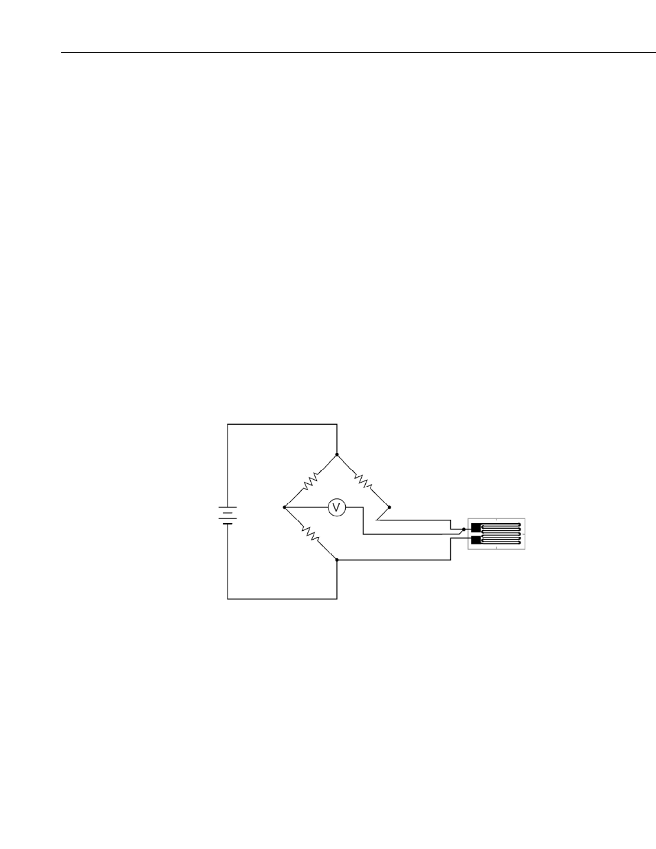
4.1 Quarter Bridge Strain with 3 Wire Strain Element
A 3-wire quarter bridge strain circuit is shown in figure 4.1-1. Strain gages are
available in nominal resistances of 120, 350, and 1000 ohms. The
4WFBSXXX model must match the nominal resistance of the gage when using
the 3-Wire circuit (e.g., the 4WFBS120 is used with a 120 ohm strain gage).
In Figure 4.1-1, R
1
and R
2
are 1000 ohm resistors making up the back plane of
the Wheatstone bridge, as is done in the TIM design. R
D
, the third resistive
element, is the complementary resistor that has a nominal resistance of the un-
strained gage. The 4
th
resistive element is the active strain gage.
Excite V
+
-
R
2
=1 K
Ω
R
1
=1 K
Ω
R
D
R
4
= Gauge
L
3
L
2
L
1
FIGURE 4.1-1. Three wire quarter bridge strain circuit
The 3-Wire gage alleviates many of the issues of the 2-Wire gage. As can be
seen in Figure 4.1-1, lead wire L
3
is in the arm of the Wheatstone bridge that
has the completion resistor while lead wire L
1
is in the arm that has the active
gage. L
2
is tied back to the input channel of the datalogger that has an input
resistance greater than 1 Gohm, thus the current flow is negligible, negating
effects of L
2
’s resistance. This circuit nulls temperature induced resistance
changes in the leads as well as reduces the sensitivity effect that the wires have
on the gauge. See Section 4.4 for more on Lead resistance effects and methods
to compensate for them.
4