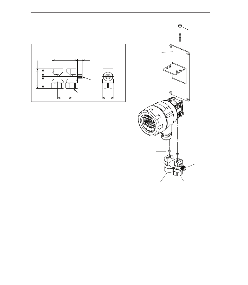
0 in. (25.4mm) mounting manifold, Lower connection diagram connection: lower side – Ashcroft GC52 - Rangeable wet/wet Differential Pressure Transmitter User Manual
Page 9
9
(2) 1/4˝ NPTF
1.4 (35)
.55 (14)
.83 (21)
1.8 (45.4)
1.0 (25.4)
Hex .83 (21)
.33 (8.5)
Equalizing
valve
• 1.0 in. (25.4mm) mounting manifold
6. PIPING
Note: High (H) and Low (L) pressure
sides of the device are marked on the
yellow label affixed to the housing of
the unit.
Install the high pressure side of the ap-
plied differential pressure in the pres-
sure inlet of the high pressure side (H)
and the low pressure side in the pres-
sure inlet of the low pressure side (L).
(Refer to the outline drawing of section 14.)
After the piping is completed check for leaks.
(1) Piping of 1.0 in (25.4mm) Manifold (
1
⁄
4
˝ npt female ports)
Use caution when installing to keep metal chips and other debris from
entering pressure transmitter. In addition, when sealing tape is used,
do not apply to last two threads at the end of the fitting
Low pressure
inlet (L)
Panel mounting
bracket
High pressure
inlet (H)
Equalizing
valve
M4 x 40
O-rings
Lower connection diagram
Connection: Lower side.
- 2089 Precision Digital Test Gauges (20 pages)
- A4A - Dial Pressure Gauge (2 pages)
- 1082 - Pressure Test Gauge (20 pages)
- 1279 - Receiver Gauges (2 pages)
- 2279 - Duratran® Pressure Transmitter (2 pages)
- 1038A - Duplex Gauge (20 pages)
- 1125 - Differential Pressure Gauge (1 page)
- 1130 - Differential Pressure Gauge (2 pages)
- 1131 - Differential Pressure Gauge (2 pages)
- 1132 - Differential Pressure Gauge (2 pages)
- 1131 - Differential Pressure Gauge (2 pages)
- 1133 - Differential Pressure Gauge (2 pages)
- 1134 - Differential Pressure Gauge (2 pages)
- 2032 - Digital Sanitary Pressure Gauge (32 pages)
- DG25 General Purpose Digital Gauge (16 pages)
- 2074 Digital Industrial Gauge (32 pages)
- 2084 Precision Digital Test Gauge (20 pages)
- A2 - Heavy industrial pressure transmitter (4 pages)
- A2X - Pressure Transmitter (2 pages)
- A4 - Pressure Transmitter (6 pages)
- G2 - High Performance Pressure Transducer (2 pages)
- GC31 - Digital Pressure Sensor (20 pages)
- GC35 - Pressure Sensor (4 pages)
- GC35 - Pressure Sensor (20 pages)
- GC51 - Industrial Rangeable Pressure Transmitter (2 pages)
- GC51 - Industrial Rangeable Pressure Transmitter (4 pages)
- GC51 - Industrial Rangeable Pressure Transmitter (32 pages)
- GC55 - Differential Pressure Transducer with Digital Display (24 pages)
- H2 - Precision Pressure Transducer (2 pages)
- K1 - Industrial Pressure Transducer (2 pages)
- KM10 - Compact Pressure Transducer (2 pages)
- KM15 - Compact Pressure Transducer (2 pages)
- KS - Sanitary Pressure Transmitter (2 pages)
- KX - Flush Mount Pressure Transmitter (2 pages)
- DM61 (8 pages)
- DM61 (20 pages)
- CXLdp - Differential Pressure Transmitter (2 pages)
- DXLdp - Differential Pressure Transmitter (2 pages)
- GC30 Ultra-Compact Differential Pressure Sensor (20 pages)
- GC52 - Rangeable wet/wet Differential Pressure Transmitter (2 pages)
- GC52 - Rangeable wet/wet Differential Pressure Transmitter (28 pages)
- GC52 - Rangeable wet/wet Differential Pressure Transmitter (16 pages)
- GL42 - Low Differential Indicating Pressure Transmitter (4 pages)
- IXLdp - Low Differential Pressure Transmitter (2 pages)