N~ rot, P. 400, D 1000 – Ashcroft GC52 - Rangeable wet/wet Differential Pressure Transmitter User Manual
Page 31: L 0.0, A 0.0, A100.0, U se, S bt, C 0.0
31
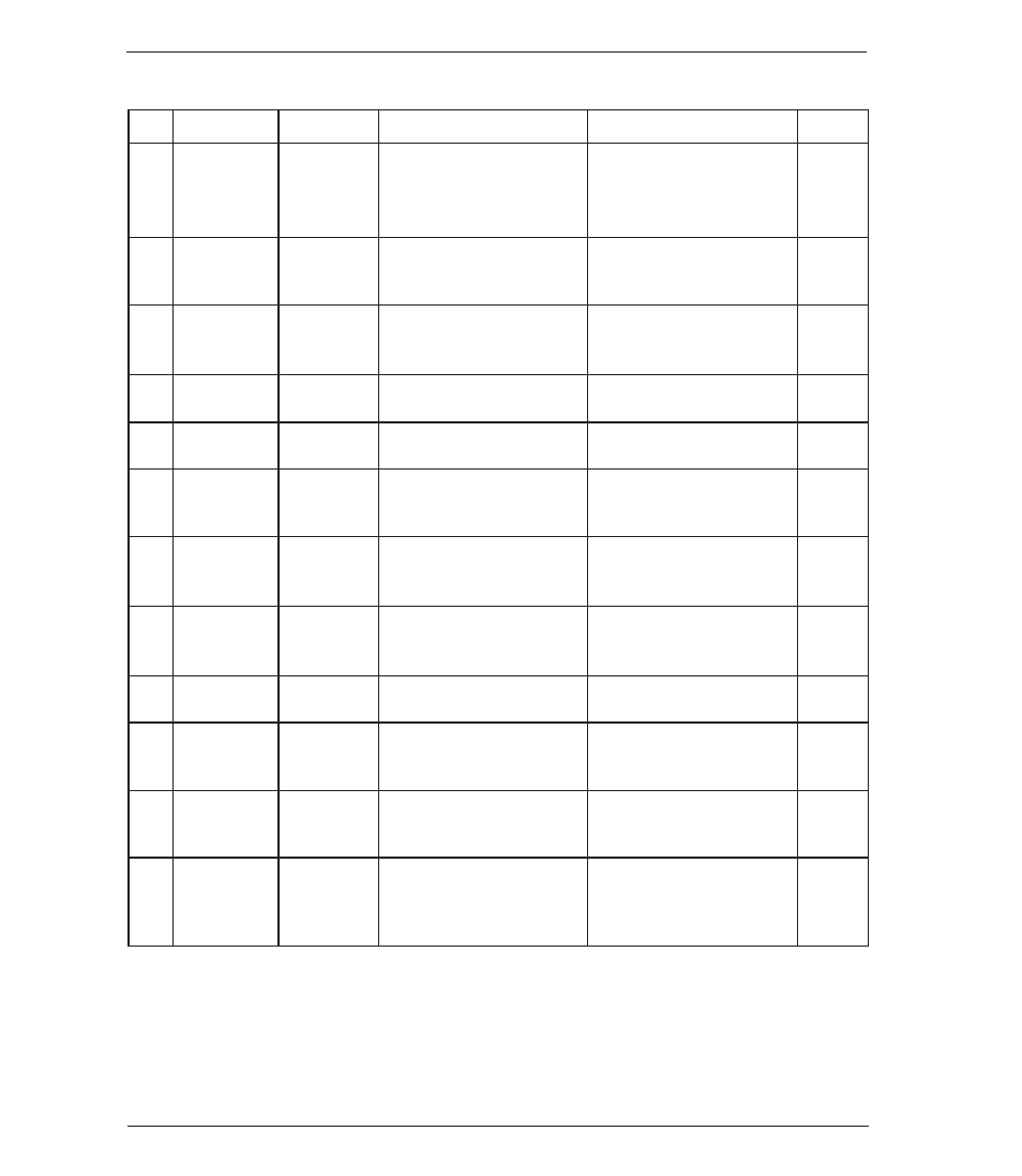
14.3 Flow Measurement/Square Root Extraction Mode
No.
Setting Item
LCD Display
Setting Description
Setting Range
Default
ባ
Display mode
n
~
roT
Selection for flow measure-
ment/ square root extraction
mode
non: Differential pressure
display mode Lin: Linear
display mode Rot: Square
root display mode
non
ተ
Maximum
differential
selection
1
p. 400
Maximum differential pres-
sure relating to the flow rate
25 to 100% F.S. of sensor
range
100.0%
of sensor
range
ቱ
Flow rate deci-
mal pt. position
D 0
Displays of value after deci-
mal point, # of digits
0,1,2,3 digit
0
ቲ
Max. momen-
tary flow
D 1000
Max. momentary of flow
using arbitrary units
0 to 1999
1000
ታ
Low cut
l 0.0
Forces display and output to
zero
0.0 to 30.0% F.S. of max.
display span
0.0
ቴ
Output zero
point
2
A 0.0
Momentary flow rate of ana-
log output zero point (4mA):
100.0% F.S.
–10 to 100% F.S. of max.
display span
0.0
ት
Output span
point
2
A100.0
Momentary flow rate of ana-
log output zero point
(20mA): 100.0% F.S.
–10 to 100% F.S. of max.
display span
100.0
ቶ
Time factor
U SE[
Measurement of max. mo-
mentary flow rate over time
selected
Seconds, minutes or hours
Sec
k
21
Flow rate vol-
ume factor
U 1
Flow rate x time selected
1,10,100,1000
1
k
22
Display
switch set-
ting
s bT
Selection of display switching
method of momentary flow
rate and integrated volume
ti = automatic
bt = manual
bt
k
23
Switch time
interval
T 5
Selection for ti: automatic
Displays switching time in-
terval in seconds
1 to 10 seconds (10 stage)
5
k
24
Loop check
3
c 0.0
Output check using arbitrary
value – displays pressure
correlating to the 4 to 20mA
signal
Display: momentary flow
rate display span
Analog output: 4 to 20mA
0.0 to 100.0%
0
(4.0mA)
(1) In the setting of a differential pressure the decimal point position is fixed for each differential pressure range. (Refer
to paragraph 12, Power-on Message). The max. differential pressure can be set from the value which is 25%F.S of
the differential pressure range above the minimum differential pressure.The values under 25%F.S. cannot be in-
creased or decreased by T, S key.
(2)
For setting zero point and span point of the analog output, input the percent value over the maximum display span
(between OFFSET and FULL SCALE). Its decimal point position can be set up to one digit after the decimal point (xx.x).
(3)
Regardless of generated differential pressure or low-cut, the loop check can be changed arbitrarily linking the mo-
mentary flow rate display with the analog output using the T, S keys. (Refer to 14.5.) This example of LCD display
shows the display set to span point.