N00 l 0 n, P0 - 20, P0- 120 – Ashcroft GC52 - Rangeable wet/wet Differential Pressure Transmitter User Manual
Page 30: A0-5 0.0
30
non
No
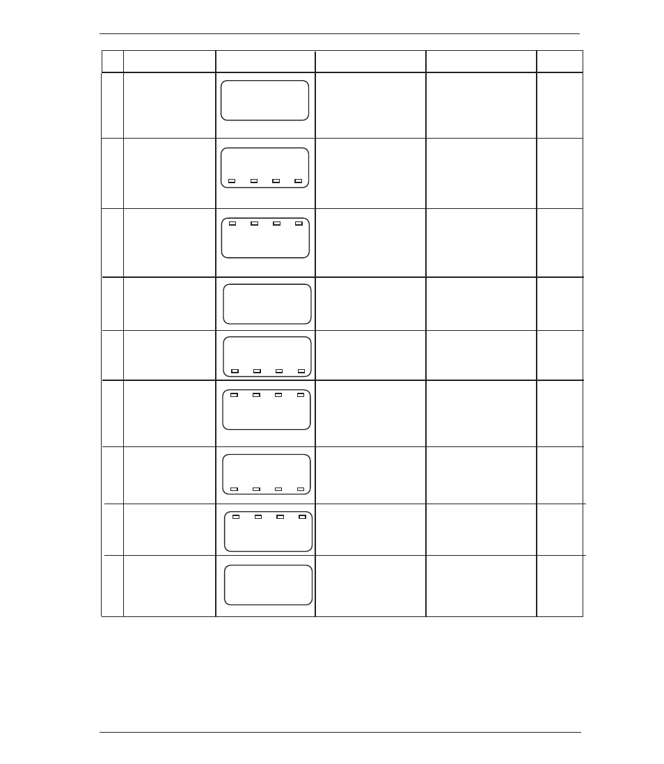
Setting Item
LCD Display
Setting Description
Setting Range
Default
ባ
n
00
l
0
n
Selection of linear
display mode: Lin
non: Differential
pressure display
mode; Lin: Linear
display mode
Display mode
-
-
0.0
ቧ
p
0 -
20
Min. differential
pressure corre-
sponding to OFF-
SET
ቪ
:20.0(inH
2
O)
Differential pres-
sure range:
0 to 75%F.S.
Min. differen-
tial pressure
(1)
100.0
ቨ
Max. differential
pressure corre-
sponding to FULL
SCALE
ቫ
:120inH
2
O)
Differential
pressure range:
25 to 100%F.S.
Max. differen-
tial pressure
(1)
p
0-
120
0
ቩ
Display after deci-
mal point Number
of digits:1(digit)
0,1,2,3 digit
Decimal point
position
d
0-00
1
d
0-0
0.0
d
0-
50.0
0
ቪ
OFFSET correspon-
ding min. differential
pressure
ቧ
: 0.0 (m)
–1999 to 1999
OFFSET
1000
ቫ
FULL SCALE corre-
sponding to max.
differential pres-
sure
ቨ
:50.0 (m)
–1999 to 1999
FULL SCALE
a
0-5
0.0
0.0
ቭ
Analog output zero
point : (4mA): 0.0
(%F.S.)
Max. display span:
–10 to 110%F.S.
Output zero
point
(2)
a
0
100.0
100.0
ቮ
Analog output span
point : (20mA):
100.0 (%F.S.)
Max. display span:
–10 to 110%F.S.
Output span
point
(2)
[
0-
50.0
0
(4.0mA)
ቯ
Arbitrary change of
linear display and
analog output:
50.0 (m), 20mA
Display: Linear dis-
play span; Analog
output: 4 to 20mA
Loop check
(3)
(1) The decimal point position is fixed for each differential pressure range. (Refer to section 10, Power-on Message).
The max. differential pressure can be set from the value which is 25%F.S above the minimum differential pressure.
The values under 25%F.S. cannot be increased or decreased by T, S key.
(2)
For setting zero point and span point of the analog output, input the percent value over the maximum display span
(between OFFSET and FULL SCALE). Its decimal point position can be set up to one digit after the decimal point
(xx.x).
(3)
Regardless of whether pressure is applied or not, the loop check can be activated which links the display and the
output allowing the operator to arbitrarily adjust the output to check the system, troubleshoot etc (using the T, S
keys), ref section 14.4. This example shows the display set to the span point.