N00 non, A0 -10.0, A0- 90.0 – Ashcroft GC52 - Rangeable wet/wet Differential Pressure Transmitter User Manual
Page 29
29
14.2
Setting Items for Linear Display Mode
(Re-scaling in arbitrary user
defined units) Set the filter before setting the linear display mode
(Refer to the preceding Section 11.1). The setting of the following table
is the Setting example 2: Linear display mode of Section 11.3.
(Arbitrary unit: m). This applies when re-scalingin arbitrary user
defined units. See Section 14.4 for full menu.
non
The setting of the following table is the Setting example
1: pressure display mode of Section 11-2. This applies when
re-scaling in “inH
2
0” units. See Section 14.4 for full menu.
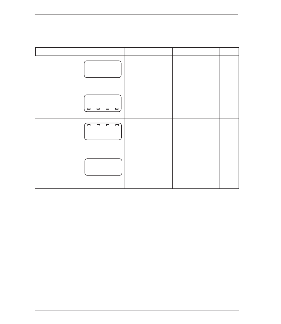
No.
Setting Item
LCD Display
Setting Description
Setting Range
Default
ባ
n
00
non
Selection of differ-
ential pressure dis-
play mode: non
non: Differential
pressure display
mode
Lin: Linear display
mode
Display mode
-
-
0.0
ቤ
a
0
-10.0
Differential pres-
sure of analog
output zero point
4mA: –10.0(%F.S.)
Differential pres-
sure range:
–10 to 110%F.S.
Output zero
point
(1)
100.0
ብ
Differential
pressure of analog
output span point
(20mA):
90.0(%F.S.)
Differential
pressure range:
–10 to 110%F.S.
Output span
point
(1)
a
0-
90.0
0.0
(4.00
mA)
ቦ
Arbitrary change of
differential pres-
sure display and
analog output:
–10.00 (psi).)
Display: Differential
pressure display
span; Analog
output: 4 to 20mA
Loop check
(2)
[
0-
10.0
(1) For setting of zero point and span point in the analog output, input the percent value over the differential
pressure range.
(2) Regardless of generated differential pressure, the loop check can be changed by arbitrarily linking the pres-
sure display with the analog output using ▲, ▼ key. (Refer to Section 14.3). This example of LCD display
shows the zero point display at the time of loop check start.